WLAN HDL Frame Detection and Signal Recovery
This example shows how to detect a frame and recover signal bits from an IEEE® 802.11ax™ standard high efficiency (HE) waveform. The example supports single-input single-output (SISO) orthogonal frequency division multiplexing (OFDM) modulation with 20 MHz bandwidth option and binary convolution coding (BCC) channel coding.
This example supports non-high throughput (Non-HT), high throughput (HT), very high throughput (VHT), and high-efficiency single user (HE-SU) frame formats. For more information on the WLAN frame formats and frame structure, see WLAN PPDU Structure (WLAN Toolbox). The Simulink® model in this example is optimized for HDL code generation and hardware implementation.
This figure shows the step-by-step operations performed to decode the signal field from the HE waveform.
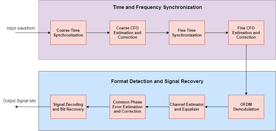
Time and frequency synchronization consists of packet detection, coarse carrier frequency offset correction, timing synchronization and fine carrier frequency offset correction. The time and frequency corrected data is then provided as input to the OFDM Demodulator block. The OFDM Demodulation block converts the time-domain signal to frequency-domain subcarriers. The Channel Estimator block uses demodulated legacy long training fields (L-LTFs) of a WLAN signal to estimate the channel frequency response. To equalize the pilot and data subcarriers of non-HT portion of the WLAN signal, the channel equalizer uses the estimated channel frequency response. The non-HT portion of the WLAN signal includes legacy SIGNAL(L-SIG) field, high-throughput SIGNAL fields 1 and 2 (HT-SIG 1 and 2), very-high-throughput SIGNAL fields A and B (VHT-SIG-A and VHT-SIG-B), and high-efficiency SIGNAL fields A and B (HE-SIG-A and HE-SIG-B).
After equalization, non-HT common phase error (CPE) estimation is performed using non-HT pilots. The estimated CPE is used to correct data subcarriers of the non-HT portion of the WLAN signal. Common phase noise error corrected data is used for frame format detection, and signal field recovery. Frame format detector and SIGNAL field recovery detects the frame format between non-HT, HT, VHT, and HE frames and decodes the transmitted bits from WLAN signal fields L-SIG, HT-SIG 1 and 2, VHT-SIG-A 1 and 2, and HE-SIG-A 1 and 2. Signal parameters such as modulation and coding scheme (MCS), physical layer convergence protocol service data unit (PSDU) length, and the channel coding type can be calculated using the decoded bits from the signal field.
Using this example you can validate the Simulink® model output at different stages by using MATLAB® functions in WLAN Toolbox™.
Model Architecture
This figure shows the high-level overview of a WLAN HE signal recovery model.
modelname = 'WLANHDLHESignalRecovery';
open_system(modelname);

open_system([modelname '/WLANHDLHESignalRecovery']);

Time and Frequency Synchronization
The WLANTimeAndFrequencySync subsystem contains four subsystems: Coarse Time Sync, Coarse CFO Estimation and Correction, Fine Time Sync, and Fine CFO Estimation and Correction. The coarse time synchronization algorithm implements a double sliding window for correlation and compared with the wlanPacketDetect (WLAN Toolbox) function. The Coarse Time Sync subsystem uses the autocorrelation of legacy short training field (L-STF) symbols to return an estimated packet-start offset.
Considering the start of the packet from the Coarse Time Sync subsystem, Coarse CFO Estimation and Correction subsystem performs autocorrelation on the input using a L-STF and averages the calculated correlation metrics over a window of the L-STF duration and compared with the wlanCoarseCFOEstimate (WLAN Toolbox) function. Then, the subsystem estimates the carrier frequency offset (CFO) by considering the angle of the resulted metric.
The Fine Time Sync subsystem takes the coarsely corrected time and frequency offset waveform for fine time offset synchronization. Then, the subsystem uses correlation with a locally generated L-LTF and synchronizes the signal and compared with the wlanSymbolTimingEstimate (WLAN Toolbox) function.
The Fine CFO Estimation and Correction subsystem takes a fine time synced waveform as an input for fine tuning the frequency offset. This subsystem estimates and corrects CFO to remove any residue left after coarse frequency correction, performs fine CFO estimation similar to coarse estimation by using the L-LTF instead of the L-STF, and estimates the frequency offset by considering the angle of the averaged correlations and compared with the wlanFineCFOEstimate (WLAN Toolbox) function.
For more information about the timing and frequency synchronization, see WLAN HDL Time and Frequency Synchronization example.
OFDM Demodulation
After the timing and frequency synchronization, the waveform is then provided as input to OFDMDemodulation subsystem. The OFDM Demodulator block converts time-domain signals to frequency-domain subcarriers. In this example, the cyclic prefix (CP) length varies for different fields in the WLAN signal. For example, the first symbol of L-LTF uses a CP length of 32 or 64, the second symbol of the L-LTF uses a CP length of 0, and the remaining fields of the WLAN signal uses a CP length of 16 for 20 MHz bandwidth. In this example, the FFT length parameter is set to 64 and the Number of left guard subcarriers and *Number of right guard subcarriers| parameters are set to 0. The OFDMDemodulationParameterCalculator MATLAB function controls the OFDM Demodulator block parameters for different fields of the WLAN packet. The subsystem demodulates L-LTF data and compared with the wlanLLTFDemodulate (WLAN Toolbox) function.
open_system([modelname '/WLANHDLHESignalRecovery/OFDMDemodulation']);

Channel Estimation and Equalization
The NonHTChannelEstAndEqualize subsystem is used for L-LTF channel estimation. The input is given to the OFDM Channel Estimator block. The OFDM Channel Estimator block implements least squares (LS) estimation for the channel estimation and performs averaging on the estimates from two L-LTF symbols of the WLAN signal. The OFDM Equalizer block uses the resultant averaged channel estimate to perform zero forcing (ZF) equalization on data. To maintain uniformity across all frame formats, the channel estimation is performed on 56 subcarriers and later only the required number of subcarriers are selected based on the detected frame format.
Common Phase Noise Estimation and Correction
The NonHTCPEEstAndCorrection subsystem estimates the common phase noise for the non-HT portion of the WLAN signal. CPE estimation requires references such as non-HT pilot positions, a non-HT pilot sequence, and pseudo-noise (PN) sequence as described in Equation 17-25 in [ 1 ]. The wlanhdlHERxParameters script initializes these known references and stores them in 1-D lookup tables in the subsystem. The PolarityGenerator subsystem gives the polarity of the pilots based on the symbol number. The reference pilots are multiplied with polarity for CPE estimation. The estimated CPE is averaged on all of the pilot subcarriers in an OFDM symbol and is used for the correction of data subcarriers of non-HT portion of the WLAN packet.
Frame Format Detection
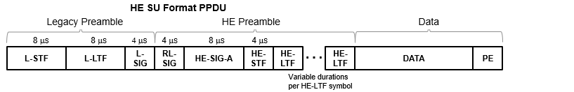
To recover the signal field information from a WLAN signal, you must decode the receiver frame format. This example supports non-HT, HT, VHT, and HE frame formats. In HE frame format, after legacy preamble, the legacy signal field is repeated and transmitted as RL-SIG.
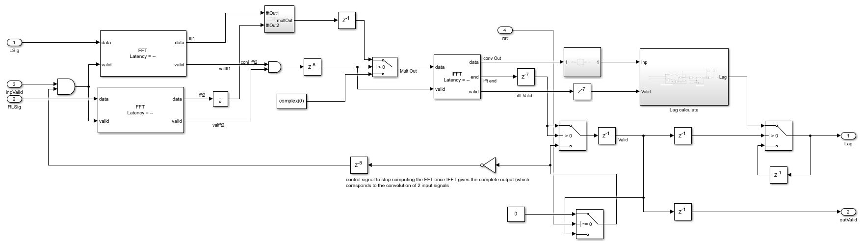
To detect the HE frame, a cross correlation is performed on the L-SIG field and RL-SIG field. If the peak is detected, then the frame is detected as an HE frame. An FFT based correlation is performed to detect the HE frame as shown in the figure
open_system([modelname '/WLANHDLHESignalRecovery/FrameFormatDetectionAndSignalRecovery/FormatIdentification/Correlator L sig and RL sig/Correlator FFT based']);
For more information about detecting other frame formats, see HDL Implementation of WLAN Receiver.
Signal Bit Recovery
The SignalRecovery subsystem recovers the header information to decode data bits from L-SIG, HT-SIG, VHT-SIG, and HE-SIG fields. The output of the NonHTCPEEstAndCorrect subsystem corresponding to signal fields is streamed into the SignalRecovery subsystem. The Symbol Demodulator block performs BPSK and QBPSK soft symbol demodulation on signal fields in the WLAN packet. The channel decoding includes Deinterleaver subsystem and Viterbi Decoder block. The Deinterleaver subsystem performs deinterleaving on the symbol demodulated data with a maximum block size of 48 and the number of columns as 16. For HE frame format, the maximum block size is 52 and the number columns is 13. The Viterbi Decoder block performs 1/2 rate Viterbi decoding on deinterleaved data. For more information on the Deinterleaver subsystem, see HDL Interleaver and Deinterleaver example. The decoded bits from the Viterbi decoder are used to compute the CRC, MCS and other information that is available in the signal fields.
Configure Input and Generate Waveform
In this example a single-user waveform is generated locally based on the chosen frame format using the wlanWaveformGenerator (WLAN Toolbox) function. The locally generated waveform is impaired by a TGax fading channel, additive white Gaussian noise (AWGN), and carrier frequency offset. To generate a waveform locally we configure a non-HT, HT, VHT, or HE packet format configuration object. The processing steps to generate the waveform are:
Generate random bits and encode them into a waveform using the waveform generator function.
Send the waveform through a TGax fading channel model.
Add carrier frequency offset and AWGN to the waveform.
frameFormat = 'HE-SU'; % Specify frame format as 'Non-HT' or 'HT-MF' or 'VHT' or 'HE-SU'
MCS = 7; % Specify MCS value from 0 to 7 - Single user
noisePower = -30; % Noise power to apply in dBW
cfo = 1000; % Carrier frequency offset Hz ranging from -156.25 kHz to 156.25 kHz (half of sub carrier spacing).
delayProfile = 'Model-A'; % TGax channel delay profile
[rxWaveform,cfg,sr,ind,indSigA] = helperwhdlHEGenerateWaveform(frameFormat,MCS,delayProfile,noisePower,cfo);
Run Simulink Model
wlanhdlHERxParameters;
validIn = true(length(rxWaveform),1);
startIn = [true;false(length(rxWaveform),1)];
stopTime = length(rxWaveform)+1500;
sim(modelname);
Generate MATLAB Reference Data
minPktLen = lstfLength*5; % Number of samples in L-STF
rxWaveLen = size(rxWaveform,1);
searchOffset = 0; % Offset from start of waveform in samples
while (searchOffset + minPktLen) <= rxWaveLen

    % Packet detection
    pktOffset = wlanPacketDetect(rxWaveform,cfg.ChannelBandwidth,searchOffset);
    if isempty(pktOffset) || (pktOffset + ind.LSIG(2) > rxWaveLen)
        error('** No packet detected **');
    end

    % Coarse frequency offset estimation and correction using L-STF
    rxLSTF = rxWaveform(pktOffset+(ind.LSTF(1):ind.LSTF(2)), :);
    coarseFreqOffset = wlanCoarseCFOEstimate(rxLSTF,cfg.ChannelBandwidth);
    rx = frequencyOffset(rxWaveform,sr,-coarseFreqOffset);
    cfoCorrectedDataMATLAB = rx(pktOffset+1:end);

    % Symbol timing synchronization
    searchBufferLLTF = rx(pktOffset+(ind.LSTF(1):ind.LSIG(2)),:);
    pktOffset = pktOffset+wlanSymbolTimingEstimate(searchBufferLLTF,cfg.ChannelBandwidth);

    % Fine frequency offset estimation and correction using L-STF
    rxLLTF = rx(pktOffset+(ind.LLTF(1):ind.LLTF(2)),:);
    fineFreqOffset = wlanFineCFOEstimate(rxLLTF,cfg.ChannelBandwidth);
    rxCFOCorrected = frequencyOffset(rx,sr,-fineFreqOffset);

    % Display estimated carrier frequency offset
    cfoCorrection = coarseFreqOffset + fineFreqOffset; % Total CFO

    break; % Front-end processing complete, stop searching for a packet
end

% Format detection
rxLLTF = rxCFOCorrected(pktOffset+(ind.LLTF(1):ind.LLTF(2)),:);
lltfDemod = wlanLLTFDemodulate(rxLLTF,cfg.ChannelBandwidth,1);
lltfChanEst = wlanLLTFChannelEstimate(lltfDemod,cfg.ChannelBandwidth);
noiseVar = wlanLLTFNoiseEstimate(lltfDemod);
rxSIGA = rxCFOCorrected(pktOffset+(ind.LSIG(1):indSigA(2)),:);
[pktFormat,cpeEst,cpeCorrData,demodOut,eqOut] = wlanFormatDetectRef(rxSIGA,lltfChanEst,noiseVar,cfg.ChannelBandwidth);

% L SIG decoding
[rxLSIGBits, failCheck, eqLSIGSym] = wlanLSIGRecover(rxCFOCorrected(pktOffset + (ind.LSIG(1):ind.LSIG(2)), :), ...
    lltfChanEst, noiseVar, cfg.ChannelBandwidth);

% HT/VHT/HE SIG decoding
switch (pktFormat)
    case 'HT-MF'
        [rxSIGABits, failCRC, eqSIGASym] = wlanHTSIGRecover(rxCFOCorrected(pktOffset + (ind.HTSIG(1):ind.HTSIG(2)), :), ...
            lltfChanEst, noiseVar, cfg.ChannelBandwidth);
    case 'VHT'
        [rxSIGABits, failCRC, eqSIGASym] = wlanVHTSIGARecover(rxCFOCorrected(pktOffset + (ind.VHTSIGA(1):ind.VHTSIGA(2)), :), ...
            lltfChanEst, noiseVar, cfg.ChannelBandwidth);
    case 'HE-SU'
        rxLSIG = rxCFOCorrected(pktOffset+(ind.LSIG(1):ind.RLSIG(2)),:);
        rxSIGA = rxCFOCorrected(pktOffset+(ind.HESIGA(1):ind.HESIGA(2)),:);
        helsigDemod = wlanHEDemodulate(rxLSIG,'L-SIG',cfg.ChannelBandwidth);
        helsigDemod = wlanHETrackPilotError(helsigDemod,lltfChanEst,cfg,'L-SIG');
        preHEChanEst = wlanPreHEChannelEstimate(helsigDemod,lltfChanEst,cfg.ChannelBandwidth);
        sigaDemod = wlanHEDemodulate(rxSIGA,'HE-SIG-A',cfg.ChannelBandwidth);
        hesigaDemod = wlanHETrackPilotError(sigaDemod,preHEChanEst,cfg,'HE-SIG-A');

        % Equalize data carrying subcarriers, merging 20 MHz subchannels
        preheInfo = wlanHEOFDMInfo('HE-SIG-A',cfg.ChannelBandwidth);
        [eqSIGASym,csi] = wlanHEEqualize(hesigaDemod(preheInfo.DataIndices,:,:), ...
            preHEChanEst(preheInfo.DataIndices,:,:), ...
            noiseVar,cfg,'HE-SIG-A');
        % Recover HE-SIG-A bits
        [rxSIGABits,failCRC] = wlanHESIGABitRecover(eqSIGASym,noiseVar,csi);
end
Comparison of MATLAB Reference with Simulink Output
Compare the output from each subsystem with the corresponding MATLAB reference function.
timeSyncOutSimulink = timeSyncDataOut(timeSyncValidOut);
timeSyncOutMATLAB = rxWaveform(pktOffset+1:end);
rmse = relativeMSE(timeSyncOutMATLAB,timeSyncOutSimulink(end-length(timeSyncOutMATLAB)+1:end));
fprintf(['MATLAB and Simulink relative MSE after Coarse time sync (packet detection): ' num2str(rmse) ' dB\n\n']);

cfoCorrectedDataSimulink = cfoCorrectedData(cfoCorrectedValid);
rmse = relativeMSE(cfoCorrectedDataMATLAB,cfoCorrectedDataSimulink);
fprintf(['MATLAB and Simulink relative MSE after Coarse CFO Estimation and correction: ' num2str(rmse) ' dB\n\n']);

fineTimeSyncOutSimulink = fineTimeSyncDataOut(fineTimeSyncValidOut);
fineTimeSyncOutMATLAB = rx(pktOffset+1:end);
rmse = relativeMSE(fineTimeSyncOutMATLAB,fineTimeSyncOutSimulink);
fprintf(['MATLAB and Simulink relative MSE after Fine time sync (Symbol Timing Estimate): ' num2str(rmse) ' dB\n\n']);

finecfoCorrectedDataSimulink = finecfoCorrectedData(finecfoCorrectedValid);
finecfoCorrectedDataMATLAB = rxCFOCorrected(pktOffset+1:end);
rmse = relativeMSE(finecfoCorrectedDataMATLAB,finecfoCorrectedDataSimulink);
fprintf(['MATLAB and Simulink relative MSE after Fine CFO Estimation and correction: ' num2str(rmse) ' dB\n\n']);

ofdmInfo = wlan.internal.vhtOFDMInfo('L-LTF',cfg.ChannelBandwidth);
ltfDemodDataSimulink = ltfDemodulatedData(ltfDemodulatedValid);
rmse = relativeMSE(lltfDemod(:)/sqrt(52),ltfDemodDataSimulink([128+ofdmInfo.ActiveFFTIndices;192+ofdmInfo.ActiveFFTIndices]));
fprintf(['MATLAB and Simulink relative MSE after LLTF Demodulation: ' num2str(rmse) ' dB\n\n']);

ltfChanEstDataSimulink = ltfChanEstData(ltfChanEstValid);
rmse = relativeMSE(lltfChanEst(:),ltfChanEstDataSimulink(2+(1:52)));
fprintf(['MATLAB and Simulink relative MSE after LTF channel estimation: ' num2str(rmse) ' dB\n\n']);

eqDataSimulink = eqDataOut(eqValidOut);
if strcmpi(pktFormat,'HE-SU')
    rmse = relativeMSE(eqOut(2+(1:48),1),eqDataSimulink(2+(1:48)));
else
    rmse = relativeMSE(eqOut(1:48,1),eqDataSimulink(2+(1:48)));
end
fprintf(['MATLAB and Simulink relative MSE after L Signal channel equalization: ' num2str(rmse) ' dB\n\n']);

fprintf('Estimated CFO from MATLAB: %5.1f Hz\n',cfoCorrection);
estimatedCFO = simOut.estimateCFO.Data(end)*sr;
fprintf(['Estimated CFO from Simulink: ' num2str(estimatedCFO) ' Hz\n\n']);

fprintf('%s packet detected from MATLAB\n',pktFormat);
if simOut.frameFormat.Data(end)==0
    fprintf('Non-HT packet detected from Simulink\n\n');
elseif simOut.frameFormat.Data(end)==1
    fprintf('HT-MF packet detected from Simulink\n\n');
elseif simOut.frameFormat.Data(end)==2
    fprintf('VHT packet detected from Simulink\n\n');
else
    fprintf('HE-SU packet detected from Simulink\n\n');
end

signalBitsSimulink = sigBits(sigBitsValid);
if isequal(rxLSIGBits(:),signalBitsSimulink(1:24))
    fprintf('Decoded L signal bits from MATLAB and Simulink are same\n\n');
else
    fprintf('Decoded L signal bits from MATLAB and Simulink are different\n\n');
end

switch (pktFormat)
    case 'HT-MF'
        if isequal(rxSIGABits(:),signalBitsSimulink(25:end))
            fprintf('Decoded HT signal bits from MATLAB and Simulink are same\n\n');
        else
            fprintf('Decoded HT signal bits from MATLAB and Simulink are different\n\n');
        end
    case 'VHT'
        if isequal(rxSIGABits(:),signalBitsSimulink(25:end))
            fprintf('Decoded VHT signal bits from MATLAB and Simulink are same\n\n');
        else
            fprintf('Decoded VHT signal bits from MATLAB and Simulink are different\n\n');
        end
    case 'HE-SU'
        if isequal(rxSIGABits(:),signalBitsSimulink(25:end))
            fprintf('Decoded HE signal bits from MATLAB and Simulink are same\n\n');
        else
            fprintf('Decoded HE signal bits from MATLAB and Simulink are different\n\n');
        end
end

fprintf(['Decoded MCS value from Simulink is ' num2str(simOut.MCS.Data(end)) '\n\n']);

% Function to calculate relative mean squared error between two signals.
function mse = relativeMSE(a,b)
% Calculate relative mean squared error
a = a(1:length(b)); % truncate a to same length as b
mse = 10*log10(sum(abs(a-double(b)).^2)/sum(abs(a).^2));
end
MATLAB and Simulink relative MSE after Coarse time sync (packet detection): -78.8008 dB

MATLAB and Simulink relative MSE after Coarse CFO Estimation and correction: -51.4796 dB

MATLAB and Simulink relative MSE after Fine time sync (Symbol Timing Estimate): -51.4796 dB

MATLAB and Simulink relative MSE after Fine CFO Estimation and correction: -37.1731 dB

MATLAB and Simulink relative MSE after LLTF Demodulation: -46.7698 dB

MATLAB and Simulink relative MSE after LTF channel estimation: -46.8275 dB

MATLAB and Simulink relative MSE after L Signal channel equalization: -36.2974 dB

Estimated CFO from MATLAB: 860.2 Hz
Estimated CFO from Simulink: 870.3396 Hz

HE-SU packet detected from MATLAB
HE-SU packet detected from Simulink

Decoded L signal bits from MATLAB and Simulink are same

Decoded HE signal bits from MATLAB and Simulink are same

Decoded MCS value from Simulink is 7
HDL Code Generation and Implementation Results
To generate the HDL code for this example, you must have the HDL Coder™ product. To generate HDL code and an HDL testbench for WLANHDLHESignalRecovery subsystem, use the makehdl and makehdltb commands. The resulting HDL code was synthesized for a Xilinx® Zynq® Ultrascale+ RFSoC ZCU111 evaluation board. The table shows the post place and route resource utilization results. The design meets timing with a clock frequency of 300 MHz for 16 bit input word length.
F = table(...
    categorical({'CLB LUT'; 'CLB Registers'; 'RAMB36'; 'RAMB18';...
    'DSP48'}),...
    categorical({'42403'; '45274'; '8'; '6'; '320'}),...
    'VariableNames',...
    {'Resources','Usage'});

disp(F);
      Resources      Usage
    _____________    _____

    CLB LUT          42403
    CLB Registers    45274
    RAMB36           8
    RAMB18           6
    DSP48            320
References
IEEE 802.11-2016 - IEEE Standard for Information technology--Telecommunications and information exchange between systems Local and metropolitan area networks--Specific requirements - Part 11: Wireless LAN Medium Access Control (MAC) and Physical Layer (PHY) Specifications.
See Also
Blocks
Functions
wlanPacketDetect(WLAN Toolbox) |wlanCoarseCFOEstimate(WLAN Toolbox) |wlanSymbolTimingEstimate(WLAN Toolbox) |wlanFineCFOEstimate(WLAN Toolbox) |wlanLLTFDemodulate(WLAN Toolbox) |wlanWaveformGenerator(WLAN Toolbox)