basebandPhaseAnalyzer
Description
Use the basebandPhaseAnalyzer object to measure the relative phase offset
between two or more channels across one or more synchronized radios. You can configure the
object to analyze capture antennas using an external or known stimulus or to analyze transmit
antennas by capturing the emitted signal using a monitor antenna.
The object connects radio application objects to antennas for phase analysis.
To set up the basebandPhaseAnalyzer object, follow these steps:
Create a
basebandTransceiverapplication object for your radio or radios. This application object configures your radio to simultaneously transmit and capture IQ waveforms over the air.If you are using multiple radios, synchronize the radio time. For details, see Time-Synchronize Operations.
Specify
basebandPhaseAnalyzerobject properties:Specify the radio or radios for phase analysis.
To perform capture antenna phase analysis, specify the radio and antenna to transmit a stimulus signal. Alternatively, you can use an external stimulus.
To perform transmit antenna phase analysis, specify the radio and antenna as a monitor to capture the transmitted signals.
To perform phase analysis, use the measureAntennaPhase
object function. For more information about how the phase analysis is performed, see Capture Calibration and Transmit Calibration.
The results of the phase analysis are estimated phase offsets for each antenna under test relative to the first antenna of the first radio. You can use these estimates to apply a correction to future transmissions or captured data.
In phase-coherent systems, you can achieve phase calibration using this method.
In systems that are not phase-coherent, the phase offset of each antenna drifts over time due to hardware and environmental factors. Rerun the function periodically or after you make changes to the hardware to maintain the accuracy of the phase calibration.
For more information, see Phase-Synchronize Operations.
Creation
Description
analyzer = basebandPhaseAnalyzer
analyzer = basebandPhaseAnalyzer(PropertyName=Value)RadioApplications=[bbtrx1,bbtrx2] specifies the baseband transceiver
objects bbtrx1 and bbtrx2 as the radio applications
for phase analysis.
Properties
Object Functions
measureAntennaPhase | Estimate relative phase offsets of transmit or capture antennas |
Examples
Create a default phase analyzer object.
bbpa = basebandPhaseAnalyzer
bbpa =
  basebandPhaseAnalyzer with properties:

       RadioApplication: {1×0 cell}
        StimulusAntenna: [0×0 string]
         MonitorAntenna: [0×0 string]
    StimulusApplication: [0×0 basebandTransceiver]
     MonitorApplication: [0×0 basebandTransceiver]
Specify a basebandTransceiver application object as the radio for phase analysis.
bbpa.RadioApplication = bbtrx;
To measure the phase offsets between capture antennas on your radio, specify a basebandTransceiver application object as the stimulus application, and specify the antenna to transmit the stimulus signal. This example uses a different radio to transmit the stimulus signal.
bbpa.StimulusApplication = bbtrx2;
bbpa.StimulusAntenna = "RF1:TX/RX";
To measure the phase offsets between transmit antennas on your radio, specify a basebandTransceiver application object as the monitor application. This example uses a different radio as a monitor.
bbpa.MonitorApplication = bbtrx2;
bbpa.MonitorAntenna = "RF1:RX2"
bbpa =
basebandPhaseAnalyzer with properties:
RadioApplication: {[1×1 basebandTransceiver]}
StimulusAntenna: "RF1:TX/RX"
MonitorAntenna: "RF1:RX2"
StimulusApplication: [1×1 basebandTransceiver]
MonitorApplication: [1×1 basebandTransceiver]
This example shows how to measure relative phase offsets between transmit antennas on a single radio using the basebandPhaseAnalyzer object. The example uses a second USRP radio to capture the monitor signal.
Create Radio Objects
Create a radio object for each radio, specifying a radio setup configuration previously saved using the Radio Setup wizard.
radio = radioConfigurations("MyRadio");
radio2 = radioConfigurations("MyRadio2");
Specify Antennas
Define the antennas under test and the monitor antenna.
antennasUnderTest = ["RF0:TX/RX" "RF1:TX/RX"];
monitorAntenna = "RF1:RX2";
Configure Baseband Transceivers
Create and configure a basebandTransceiver application object for each radio. Use the same RF properties on both radios. Specify all RF properties using the PropertyName=Value syntax and preload the FPGA image.
transmitGain = 20;
captureGain = 30;

bbtrx = basebandTransceiver(radio, ...
    Preload=true, ...
    TransmitAntennas=antennasUnderTest, ...
    TransmitRadioGain=transmitGain);

bbtrx2 = basebandTransceiver(radio2, ...
    Preload=true, ...
    CaptureAntennas=monitorAntenna, ...
    CaptureRadioGain=captureGain);
Synchronize Radio Time
Synchronize both radios to a common time using the next PPS signal.
tLastPPS = getTimeLastPPS(radio);
while tLastPPS == getTimeLastPPS(radio)
    pause(0.1)
end
setTimeNextPPS(radio,0);
setTimeNextPPS(radio2,0);
Verify that the radio time is synchronized.
pause(1.1)
tLastPPS1 = getTimeLastPPS(radio);
tLastPPS2 = getTimeLastPPS(radio2);
isequal(tLastPPS1,tLastPPS2)
ans = logical
   1
If the radio time synchronization is unsuccessful, rerun this section.
Estimate Relative Phase Offsets
Create a phase analyzer object.
bbpa = basebandPhaseAnalyzer(RadioApplication=bbtrx, ...
    MonitorApplication=bbtrx2,MonitorAntenna=monitorAntenna);
Estimate the relative phase offsets of the specified transmit antennas and plot the measurement results.
[phase,results] = measureAntennaPhase(bbpa,"transmit")phase = 1×1 cell array
{[0 -60.0394]}
results = 1×1 cell array
    {72×2 double}
This example shows how to measure relative phase offsets between capture antennas on a single radio using the basebandPhaseAnalyzer object. The example uses a second USRP radio to transmit the stimulus signal.
Create Radio Objects
Create a radio object for each radio, specifying a radio setup configuration previously saved using the Radio Setup wizard.
radio = radioConfigurations("MyRadio");
radio2 = radioConfigurations("MyRadio2");
Specify Antennas
Define the stimulus antenna and the antennas under test.
antennasUnderTest = ["RF0:RX2" "RF1:RX2"];
stimulusAntenna = "RF1:TX/RX";
Configure Baseband Transceivers
Create and configure basebandTransceiver application objects for each radio. Use the same RF properties on both radios. Specify all RF properties using the PropertyName=Value syntax and preload the FPGA image.
transmitGain = 20;
captureGain = 30;

bbtrx = basebandTransceiver(radio, ...
    Preload=true, ...
    CaptureAntennas=antennasUnderTest, ...
    CaptureRadioGain=captureGain);

bbtrx2 = basebandTransceiver(radio2, ...
    Preload=true, ...
    TransmitAntennas=stimulusAntenna, ...
    TransmitRadioGain=transmitGain);
Synchronize Radio Time
Synchronize both radios to a common time using the next PPS signal.
tLastPPS = getTimeLastPPS(radio);
while tLastPPS == getTimeLastPPS(radio)
    pause(0.1)
end
setTimeNextPPS(radio,0);
setTimeNextPPS(radio2,0);
Verify that the radio time is synchronized.
pause(1.1)
tLastPPS1 = getTimeLastPPS(radio);
tLastPPS2 = getTimeLastPPS(radio2);
isequal(tLastPPS1,tLastPPS2)
ans = logical
   1
If the radio time synchronization is unsuccessful, rerun this section.
Estimate Relative Phase Offsets
Create a phase analyzer object.
bbpa = basebandPhaseAnalyzer(RadioApplication=bbtrx, ...
    StimulusApplication=bbtrx2,StimulusAntenna=stimulusAntenna);
Estimate the relative phase offsets of the specified capture antennas and plot the measurement results.
phase = measureAntennaPhase(bbpa,"capture")phase = 1×1 cell array
{[0 171.6380]}
This example shows how to measure relative phase offsets between capture antennas using the basebandPhaseAnalyzer object. The example uses a USRP N321 and USRP N320 radio with LO sharing configured.
Create Radio Objects
Create a radio object for each radio, specifying a radio setup configuration previously saved using the Radio Setup wizard.
radio1 = radioConfigurations("MyN321");
radio2 = radioConfigurations("MyN320");
Specify Antennas
Define the stimulus antenna and the antennas under test.
stimulusAntenna = "RF1:TX/RX";
antennasUnderTest_radio1 = "RF0:RX2";
antennasUnderTest_radio2 = ["RF0:RX2" "RF1:RX2"];
Configure Baseband Transceivers
Create and configure basebandTransceiver application objects for each radio. Use the same RF properties on both radios. Specify all RF properties using the PropertyName=Value syntax and preload the FPGA image.
transmitGain = 20;
captureGain = 30;

bbtrx1 = basebandTransceiver(radio1, ...
    Preload=true, ...
    CaptureAntennas=antennasUnderTest_radio1, ...
    CaptureRadioGain=captureGain, ...
    TransmitAntennas=stimulusAntenna, ...
    TransmitRadioGain=transmitGain);

bbtrx2 = basebandTransceiver(radio2, ...
    Preload=true, ...
    CaptureAntennas=antennasUnderTest_radio2, ...
    CaptureRadioGain=captureGain);
Synchronize Radio Time
Synchronize both radios to a common time using the next PPS signal.
tLastPPS = getTimeLastPPS(radio1);
while tLastPPS == getTimeLastPPS(radio1)
    pause(0.1)
end
setTimeNextPPS(radio1,0);
setTimeNextPPS(radio2,0);
Verify that the radio time is synchronized.
pause(1.1)
tLastPPS1 = getTimeLastPPS(radio1);
tLastPPS2 = getTimeLastPPS(radio2);
isequal(tLastPPS1,tLastPPS2)
ans = logical
   1
If the radio time synchronization is unsuccessful, rerun this section.
Estimate Relative Phase Offsets
Create a phase analyzer object.
bbpa = basebandPhaseAnalyzer(RadioApplication={bbtrx1,bbtrx2}, ...
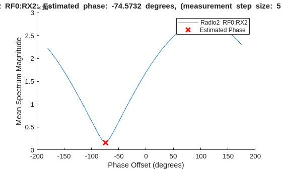
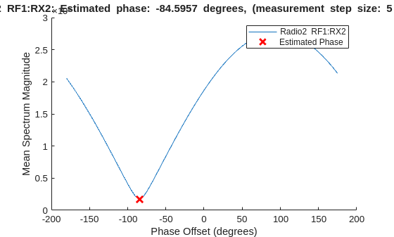
StimulusApplication=bbtrx1,StimulusAntenna=stimulusAntenna);Estimate the relative phase offsets of the specified capture antennas and plot the measurement results.
phase = measureAntennaPhase(bbpa,"capture",PlotResult=true, ...
    Antennas={antennasUnderTest_radio1 antennasUnderTest_radio2});
Display Results
Display the measured phase offsets in degrees.
disp("Measured phase estimates: ["+num2str(phase{1}(1))+" " + ...
    ""+num2str(phase{2}(1))+", "+num2str(phase{2}(2))+"]")
Measured phase estimates: [0 -74.5732, -84.5957]
Algorithms
Version History
Introduced in R2026a