Connect and Synchronize Multiple NI USRP Radios
This example shows how to connect and time-synchronize two NI USRP™ radios and capture data over the air.
Introduction
In this example, you use a shared reference clock and time source to synchronize two USRP N320/N321 radios. You then configure the radios as baseband receivers to capture a wideband spectrum by combining received data from each using a multiband combiner. The example then plots the combined wideband spectrogram of the captured data.
For an example of how to capture a wideband spectrum on a single NI USRP radio, see Capture Wideband Spectrum by Combining Data from Multiple Antennas.
For more information about synchronization features on NI USRP radios, see Time-Synchronize Operations.
Set Up Radios
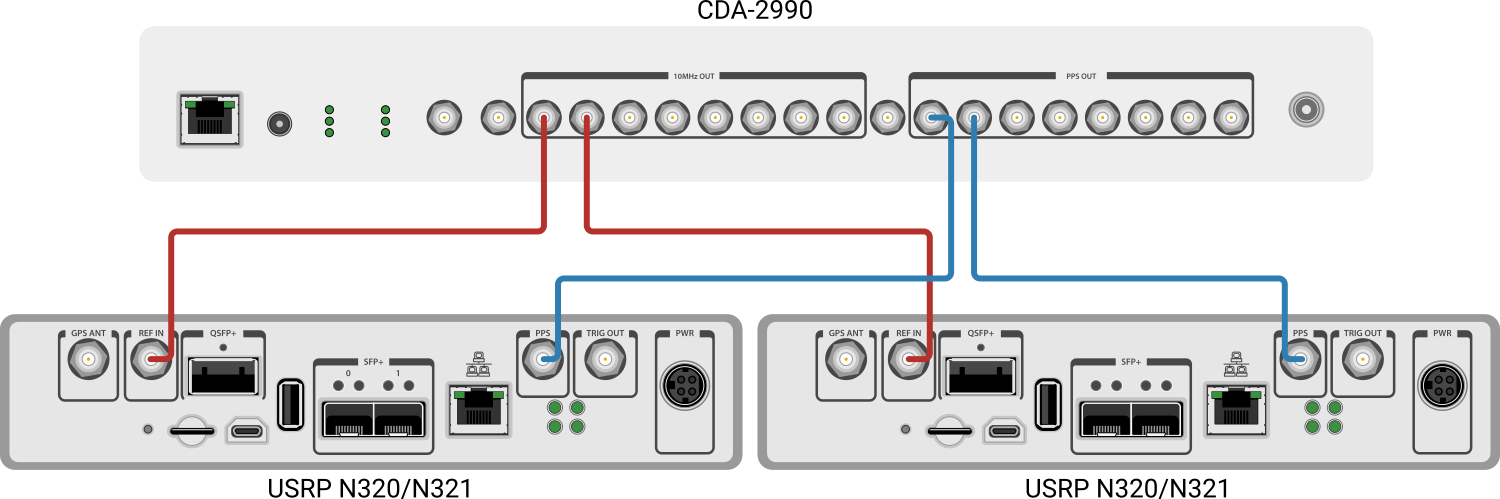
NI USRP radios synchronize their clocks and time using a 10 MHz reference clock and a pulse per second (PPS) signal. To synchronize two radios, the radios must share a common clock and time source. One option is to use an OctoClock CDA-2990 clock distribution module, which can provide up to eight 10 MHz clock reference and PPS signals. The diagram shows how to connect this module to two USRP N320 or N321 radios. You can connect other NI USRP radios in a similar way.
Use the Radio Setup wizard to set up both radios and save a radio configuration for each. In the Configure Radio step, select the option that enables you to configure the synchronization options. Use the dropdown menus to set the clock and time sources to external.
Call the radioConfigurations function. The function returns all available radio setup configurations that you saved using the Radio Setup wizard.
savedRadioConfigurations = radioConfigurations;
To update the dropdown menu with your saved radio setup configuration names, click Update. Then, use the radioConfigurations function to create a radio object for each of the two radios you select to use with this example.
savedRadioConfigurationNames = [string({savedRadioConfigurations.Name})];
 radio1 = radioConfigurations(
 savedRadioConfigurationNames(1));
radio2 = radioConfigurations(
savedRadioConfigurationNames(1));
radio2 = radioConfigurations( savedRadioConfigurationNames(2));
Configure Baseband Receivers
Set Sample Rate and Bandwidth
To capture the largest combined bandwidth, set the sample rate to the maximum supported value for your radio. Choose a single antenna bandwidth less than or equal to the maximum instantaneous bandwidth of your radio and less than the chosen sample rate to reduce aliasing effects.
To obtain the maximum sample rate and instantaneous bandwidth available for your radio, call the hMaxSampleRate and hMaxBandwidth helper functions with the name of your radio setup configurations. Alternatively, you can set custom values.
maxSampleRate = hMaxSampleRate(radio1.Name); radio1SampleRate =maxSampleRate; radio2SampleRate =
maxSampleRate; maxBandwidth = hMaxBandwidth(radio1.Name); singleAntennaBandwidth =
maxBandwidth;
Set Antennas
Set the antennas for each radio. To update the dropdown menu with antennas that support different center frequencies, call the hIndependentFrequencyCaptureAntennas helper function with the name of your radio setup configurations. Then select the antennas to use with this example.
[firstAntennaSelection, secondAntennaSelection] = hIndependentFrequencyCaptureAntennas(radio1.Name); radio1Antennas = [firstAntennaSelection(1),
secondAntennaSelection(1)]; [thirdAntennaSelection, fourthAntennaSelection] = hIndependentFrequencyCaptureAntennas(radio2.Name); radio2Antennas = [
firstAntennaSelection(1),
secondAntennaSelection(1)];
Set Data Types
Because the multiband combining operation (after capture) requires double-precision or single-precision input data, set the data type to single precision.
radio1DataType = "single";
radio2DataType = "single";
Set Gain
Set the gain for each radio according to the local signal strength.
radio1Gain =30; radio2Gain =
30;
Set Center Frequency
Set the center frequency for each antenna by shifting the center frequency of the combined band by half of the single antenna bandwidth.
centerFrequency =2.4e9; radio1CenterFrequency = [centerFrequency-1.5*singleAntennaBandwidth, ... centerFrequency-0.5*singleAntennaBandwidth]; radio2CenterFrequency = [centerFrequency+0.5*singleAntennaBandwidth, ... centerFrequency+1.5*singleAntennaBandwidth];
Configure Radios as Baseband Receivers
Create a basebandReceiver object for each radio, setting the RF properties to the values you have selected. Set the Preload name-value argument to true to load the application onto the radio during object creation. This setting enables synchronization by preventing the radio time from being reset when you first call the capture function in a later step. Because the object requires exclusive access to radio hardware resources, before running this example for the first time, clear any other object associated with these specified radios. In subsequent runs, to speed up the execution time of the example, reuse your new workspace object. You can update the CenterFrequency and RadioGain properties without affecting the time synchronization.
if ~exist("bbrx1","var")
    bbrx1 = basebandReceiver(radio1,Preload=true, ...
        Antennas=radio1Antennas, ...
        CaptureDataType=radio1DataType, ...
        CenterFrequency=radio1CenterFrequency, ...
        RadioGain=radio1Gain, ...
        SampleRate=radio1SampleRate);
end
if ~exist("bbrx2","var")
    bbrx2 = basebandReceiver(radio2,Preload=true, ...
        Antennas=radio2Antennas, ...
        CaptureDataType=radio2DataType, ...
        CenterFrequency=radio2CenterFrequency, ...
        RadioGain=radio2Gain, ...
        SampleRate=radio2SampleRate);
end
Time-Synchronize Radios
To synchronize both radios to use a common radio time, set the radio time on both radios to the same value on the next PPS signal. First, specify the value you will set the radio time to. This example uses zero.
newRadioTime = 0;
Wait for the next pulse PPS signal. Since the radios share a PPS signal, use the getTimeLastPPS function to monitor the signal on one of the radios.
lastPPSTime = getTimeLastPPS(radio1);
When a PPS signal is detected, you have one second to set a new radio time. Check for a new signal every 0.1 seconds, then use the setTimeNextPPS function to set the radio time on both radios to 0.
while lastPPSTime == getTimeLastPPS(radio1)
    pause(0.1)
end
setTimeNextPPS(radio1,newRadioTime);
setTimeNextPPS(radio2,newRadioTime);
To verify that the radios are synchronized, wait for the next PPS signal and check that the radio time on each radio has been reset to zero. If the synchronization has not been successful, run this code section again.
while getTimeLastPPS(radio1) ~= newRadioTime
    pause(0.1)
end
if getTimeLastPPS(radio2) ~= newRadioTime
    error("Radios not synchronized")
end
Because each antenna captures data at a different center frequency, the phase of the signals cannot be synchronized.
Other applications, such as multiple-input multiple-output (MIMO) and direction of arrival (DOA), capture or transmit data at the same center frequency and require knowledge of the phase relationship between channels. If your application requires phase coherent channels, you can use LO sharing with a radio that supports this feature. For more information, see Phase-Synchronize Operations. Or, you can use a radio with a front end that provides built-in phase coherence, such as in the Estimate Direction of Arrival Using MUSIC Algorithm and TwinRX Daughterboards example.
Capture IQ Data and Combine in Loop
Use the background capture capability to capture IQ data in parallel with combining the data from a previous capture in a loop.
To capture IQ data from the specified antennas in the background, call the capture function on the basebandReceiver objects, bbrx1 and bbrx2. Specify a capture length of 5 milliseconds and set the Background name-value argument to true. Schedule the capture operation to start 1 second in the future to account for latency in the capture call and communication with the radios.
captureLength = milliseconds(5);
captureTimeOffset = 1;
captureTime = getRadioTime(radio1)+captureTimeOffset;
capture(bbrx1,captureLength,Background=true,StartTime=captureTime);
capture(bbrx2,captureLength,Background=true,StartTime=captureTime);
Create a comm.MultibandCombiner System object™ to combine the captured data from each antenna.
mbc = comm.MultibandCombiner( ...
    InputSampleRate=bbrx1.SampleRate, ...
    FrequencyOffsets=([bbrx1.CenterFrequency-centerFrequency,bbrx2.CenterFrequency-centerFrequency]), ...
    OutputSampleRateSource="Auto");
Set the stopTime variable to repeatedly capture and combine IQ data for 20 seconds. Alternatively, set the value to Inf to continually capture and plot the combined spectrum.
stopTime = 20;
Use the hStopCaptureButton helper function to create a figure with a Stop button. Clock the button to set the stopCapture variable to true and exit the loop before the stopTime.
stopCaptureLoop = false;
buttonFigure = hStopCaptureButton("stopCaptureLoop");
startTime = tic;
Set the capture loop to stop when the time elapses or the Stop button is pressed.
while(toc(startTime) < stopTime && ~stopCaptureLoop)Use the isCapturing function to wait until the capture is finished. Include a 10 millisecond pause in the while-loop to avoid excessive polling.
    while isCapturing(bbrx1) || isCapturing(bbrx2)
        pause(0.1);
    end
When the capture has completed, retrieve IQ data using the captureOutputs function. Combine data from both radios into a single matrix.
    radio1Data = captureOutputs(bbrx1);
    radio2Data = captureOutputs(bbrx2);
    data = [radio1Data,radio2Data];
Start the next capture in the background while the IQ data from the previous capture is combined.
    captureTime = getRadioTime(radio1)+0.5;
    capture(bbrx1,captureLength, ...
        Background=true,StartTime=captureTime);
    capture(bbrx2,captureLength, ...
        Background=true,StartTime=captureTime);
Filter and Combine Captured Data
To reduce aliasing effects, filter the captured data to the selected bandwidth. Use the comm.MultibandCombiner System object and combine the captured data from each antenna. Reset the object after use.
    filteredData = lowpass(data, ...
        singleAntennaBandwidth/2,bbrx1.SampleRate);
    combinedData = mbc(filteredData);
    mbcInfo = info(mbc);
    reset(mbc);
    resampledData = resample(combinedData, ...
        4*singleAntennaBandwidth,mbcInfo.OutputSampleRate);
Plot Spectrogram
Plot the spectrogram of the resampled data. The example uses 4096 FFT points and a 50% overlapping Hann window of length equal to the length of the resampled data divided by 4096. Alternatively, you can experiment with custom values.
window =hann(floor(length(resampledData)/4096)); nOverlap =
floor(length(window)/2); nFFT =
4096; spectrogram(resampledData,window,nOverlap, ... nFFT,4*singleAntennaBandwidth,"centered");
To ensure updates to the figure are displayed, use the drawnow function.
    drawnow;
end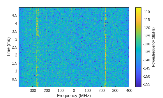
When the loop ends, close the button figure.
% If stopCaptureLoop is false, the button figure remains open
if ~stopCaptureLoop
    close(buttonFigure);
end
Further Exploration
As an alternative to synchronizing the radios using an external clock and time source, you can use one of the following options.
Most USRP radios have a GPS disciplined oscillator (GPSDO) onboard or available as an add-on. The GPSDO provides a 10 MHz reference and PPS signal that you can synchronize using GPS.
Some USRP radios, such as the USRP X300/X310, can export their clock and time references, which you can provide as an external clock and time source for other radios.