3-D Modeling, CAD Files, and Fabrication
Create your own customized 2-D and 3-D geometry. Import and export CAD files for antenna design, large structures, and PCB fabrication. Define the feed for this arbitrary element and analyze the antenna or array by using analysis functions.
Create and combine geometric shapes for PCB antennas. Select PCB antenna connectors and manufacturing services. Write Gerber files for PCB antenna manufacturing.
Categories
- 3-D Modeling
Shapes and boolean operations, create antenna from shapes, conformal array of shapes and antennas
- CAD File Import and Export
Stereolithography (STL), STEP, IGES, glTF, and Gerber files
- PCB Antenna Design and Fabrication
PCB antennas, Gerber file writer and reader, RF connectors, manufacturing services
Featured Examples
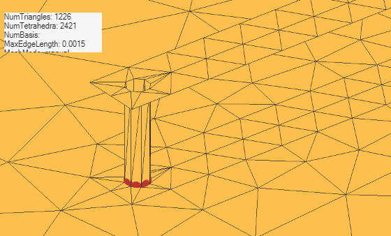
Model Coaxial Gap Feed for Probe-Fed Patch Antenna
Comparison of a standard delta-gap probe feed model and a finite-gap coaxial feed model for a patch antenna.
- Since R2025a
- Open Live Script
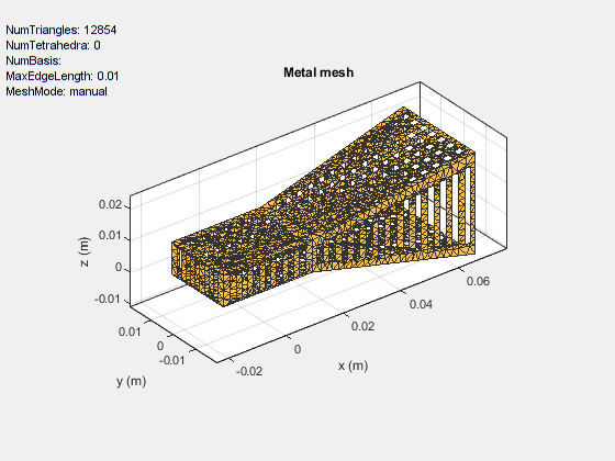
Design and Analyze Perforated Horn Antenna for RF Applications
Design a perforated horn antenna suited for RF applications using 3-D modeling features of the Antenna Toolbox™.
- Since R2024b
- Open Live Script
Train Machine Learning Model for Analysis of Custom Antenna
Apply machine learning to antenna analysis: a general recipe that you can use to train machine learning models to characterize antenna structures modeled and simulated in Antenna Toolbox™.
- Since R2023b
- Open Live Script
Design And Analyze Spherically Capped Biconical Antenna
Design spherically capped bicone antenna using 3-D modeling features and analyze its performance in 900 MHz to 15 GHz frequency range.
- Since R2023b
- Open Live Script
Analysis of Ultrawideband Trident Inset-Fed Monopole Antenna with Conical Ground
Design trident inset-fed monopole antenna using 3-D modeling features and analyze its performance over a conical ground plane.
- Since R2023b
- Open Live Script
Design and Analysis of Diamond-Shaped PCB Antenna for Ultra-Wideband Applications
Create the diamond-shaped ultra-wideband (UWB) antenna described in [1] with a modified ground plane. It analyzes this antenna over an ultra-wide frequency range of 100 MHz to 15 GHz. UWB antennas are in high demand for various applications, such as wireless communications, medical imaging, radar, and indoor positioning. This demand is due to their ability to enable a high data transmission rate and low power consumption.
Design Series-Fed Patch Antenna Array for 5G Base Station
Design and analyze a series fed patch antenna array at 28 GHz. The array has 64 antenna elements arranged in 8-by-8 configuration and is used as a 5G mobile base station antenna at 28 GHz. The phased array steers its beam along the horizontal axis to provide coverage in different directions.
PCB Antenna for USB Dongle and BLE Applications
Design and analyze a PCB antenna for USB dongle and BLE applications at 2.4 GHz.
Miniaturize Patch Antennas Using Metamaterial-Inspired Technique
Design a miniaturized patch antenna at 2.4 GHz with a complementary split-ring resonator (CSRR) loading plane and evaluate its performance, with results as published in [1]. The antenna is miniaturized by shrinking its circular patch structure from the original radius of 23.1 mm to 6 mm.
Design and Analysis of Compact Ultra-Wideband MIMO Antenna Array
Design and analyze a compact ultra-wideband (UWB) multiple-input multiple-output (MIMO) antenna array presented in [1]. The American Federal Communications Commission (FCC) allowed commercial use in the 3.1 GHz to 10.6 GHz frequency range starting from 2002. Since then, researchers have worked to develop antenna technology for this ultra wide frequency range. The main challenge in designing a UWB antenna with such a wide bandwidth is the multipath fading. A popular solution to overcome this fading effect is to use MIMO antenna array technology, which also increases the channel capacity of UWB systems.
Design and Analysis Using PCB Antenna Designer
Design, validate, analyze, and export 1-by-2 H-notch linear antenna array.
Create Antenna Model from Gerber Files
Create an antenna model from Gerber files and subsequently analyze the antenna. The Gerber file format is used in printed circuit board (PCB) manufacturing and is defined in the RS-274X standard which is the newer extended Gerber format. The Antenna Toolbox™ supports the newer RS-274X format both to generate Gerber files from an antenna model as well as to create an antenna model from a set of Gerber files.
Import and Analyze Custom 3-D Antenna Geometry
Simulate a 3-D custom antenna geometry from an STL (stereolithography) file. An STL file is a tessellation of a structure in 3-D space using triangles. To simulate a 3-D custom antenna geometry, use the customAntennaStl object. This object allows you to simulate a custom 3-D geometry from an *.stl file.
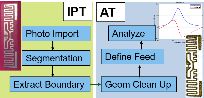
Antenna Model Generation and Full-Wave Analysis From Photo
Demonstrates the process of using a photograph of a planar antenna to generate a viable antenna model and its subsequent analysis for port, surface and field characteristics. The Image Segmenter app is used to perform segmentation on the image of an RFID tag, and the resulting boundaries are used to set up the antenna model in Antenna Toolbox™. An initial impedance analysis is done over a frequency range to understand the port characteristics of the antenna. After determining the resonant frequency, the current and far-field pattern are calculated and plotted.
Model and Analyze Planar Photonic Band Gap Structure
Create and analyze microwave planar Photonic Band Gap (PBG) structures using Antenna Toolbox™. Photonic Band Gap structures consist of a periodic lattice which provides effective and flexible control of the Electromagnetic wave propagation in one or multiple directions. Microwave planar PBG structures were first introduced around the year 2000 by Prof. Itoh and his group. These structures create a stop band over a certain frequency range and are easy to implement by cutting periodic patterns on the metal ground plane.
Modeling and Analysis of Probe-Fed Stacked Patch Antenna
The steps to model and analyze a probe-fed stacked patch antenna. The standard rectangular microstrip patch antenna has a narrow impedance bandwidth typically less than 5%. The stacked patch configuration is one of the ways of increasing the impedance bandwidth of these antennas to be greater than 25% [1]. There are different ways of designing stacked patches, primarily differing in the way their feed is designed [2]. The two types of feeding mechanisms are probe-feed and aperture coupled. These two mechanisms have a role in the impedance bandwidth behavior as well as the radiation characteristics of the antenna.
Model and Analyze Dual Polarized Patch Microstrip Antenna
Design and measure a wideband dual polarized microstrip antenna that finds its use at the base station of a cellular system. In order to achieve the wideband characteristics, this design considers a slot coupled patch antenna structure.
Design Microstrip Patch at 77 GHz for Automotive Radar Receiver
Create, model, and analyze an inset-fed microstrip patch antenna at high frequencies. As the frequency of operation increases to millimeter waves, the antenna sizes decrease and the antennas are fabricated on printed circuit boards (PCBs). Such printed antennas are of light weight, are inexpensive, easy to integrate, and are widely used as components in a radar. The antenna designed in this example operates at a frequency of 77 GHz and is used in an automotive radar receiver.
MATLAB Command
You clicked a link that corresponds to this MATLAB command:
Run the command by entering it in the MATLAB Command Window. Web browsers do not support MATLAB commands.
Seleziona un sito web
Seleziona un sito web per visualizzare contenuto tradotto dove disponibile e vedere eventi e offerte locali. In base alla tua area geografica, ti consigliamo di selezionare: .
Puoi anche selezionare un sito web dal seguente elenco:
Come ottenere le migliori prestazioni del sito
Per ottenere le migliori prestazioni del sito, seleziona il sito cinese (in cinese o in inglese). I siti MathWorks per gli altri paesi non sono ottimizzati per essere visitati dalla tua area geografica.
Americhe
- América Latina (Español)
- Canada (English)
- United States (English)
Europa
- Belgium (English)
- Denmark (English)
- Deutschland (Deutsch)
- España (Español)
- Finland (English)
- France (Français)
- Ireland (English)
- Italia (Italiano)
- Luxembourg (English)
- Netherlands (English)
- Norway (English)
- Österreich (Deutsch)
- Portugal (English)
- Sweden (English)
- Switzerland
- United Kingdom (English)


