Crossed-Dipole (Turnstile) Antenna and Array
The turnstile antenna invented in 1936 by Brown [1] is a valuable tool to create a circularly-polarized pattern (RHCP or LHCP). It is commonly used in mobile communications.
Turnstile Antenna Parameters
The turnstile antenna usually operates at the fundamental (series) resonance of the dipole-like antenna. In order to achieve circular polarization, the turnstile antenna has either an external quadrature hybrid as a 90 degree power divider/combiner or an internal built-in phase shifting network. In this example, the antenna is designed for 300 MHz. The spacing between the two crossed dipoles is of the order of lambda/50.
freq = 300e6;
lambda = 3e8/freq;
offset = lambda/50;
spacing = lambda/2;
length = lambda/2.1;
width = lambda/50;
anglevar = 0:10:180;
freqrange = 200e6:2e6:400e6;
gndspacing = lambda/4;
Turnstile Antenna
The turnstile antenna is created by using two identical dipoles oriented at right angles to each other.The default crossed dipole catalog element is rotated by 90 degrees to set it up in the X-Y plane. The desired 90 degree phase shift is obtained by specifying the phase shift of the second dipole to 90 degree
d  = dipole(Length=length, Width=width);
ant= dipoleCrossed(Element=d, Tilt=90, TiltAxis=[0 1 0]);
figure
show(ant)

The plot below shows the return loss of the first element of the turnstile antenna. As the two elements are identical, the return loss of the second dipole should be the same. The elements are well matched to a 75 ohm system.
figure
returnLoss(ant, freqrange, 75);

The radiation pattern of the crossed-dipole is symmetric about the x-y plane and the peak value is close to 2.1dBi.
pattern(ant, freq);

The axial ratio of the turnstile is calculated and plotted in the two principal planes. As can be seen in the plot, the axial ratio is less than 3dB, around 45 degrees on either side of boresight. This indicates that the antenna gives close to circular polarization in the 90 degree region around the boresight.
AR1 = axialRatio(ant, freq, 0, anglevar);
AR2 = axialRatio(ant, freq, 90, anglevar);
figure;
plot(anglevar, AR1, 'r*-', anglevar, AR2, 'ro-');
axis([0 180 0 5]);
grid on;
xlabel("elevation (deg)")
legend("az = 0", "az = 90")
ylabel("Axial ratio (dB)");
title("turnstile antenna")

3 Element Turnstile Array
The figure below shows a three element turnstile array. The spacing between the elements is chosen to be lambda/2. The first turnstile element is at the origin while the other two elements are one half wavelength away.
arr=linearArray(Element=ant, ElementSpacing=spacing, NumElements=3);
show(arr)

The plot below shows the directivity of the resultant array. The peak value is close to 6.8 dBi. The pattern is still symmetric about the X-Y plane.
pattern(arr, freq);

4 Element Turnstile Array with Reflector
To prevent loss of radiation below the x-y plane, a reflector can be added. Below is a four element turnstile array backed by a reflector. The reflector length is twice the wavelength while the width is a wavelength. The spacing between the reflector and the antenna is quarter wavelength. The array is symmetric about the origin, so there is no element at the origin.
r = reflector(Exciter=ant, GroundPlaneLength=spacing,...
     GroundPlaneWidth=lambda, Spacing=gndspacing);
refarray =linearArray(Element=r, ElementSpacing=spacing, NumElements=4);
show(refarray)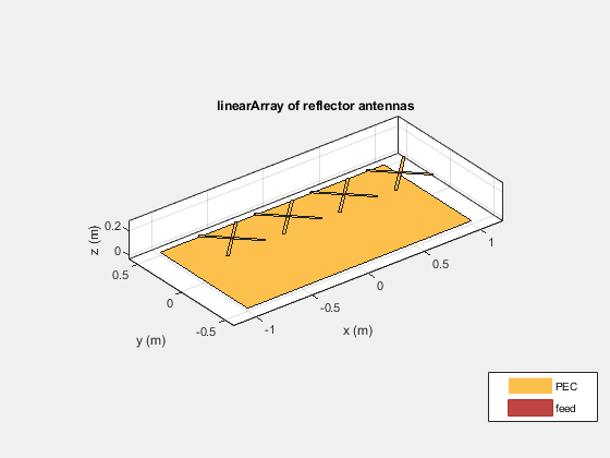
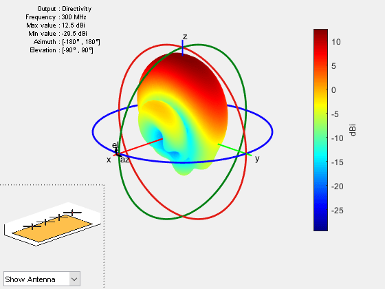
The plot below shows the radiation pattern of the four element array. The peak value is close to 12.6 dBi. The presence of the reflector ensures that most of the energy is radiated along the positive z-axis.
figure
pattern(refarray, freq);
The plot below shows the pattern slice at zero azimuth angle.
figure
patternElevation(refarray, freq);

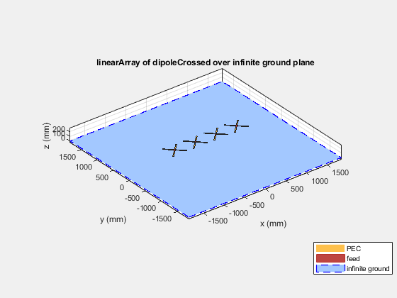
4 Element Turnstile Array over Infinite Ground Plane
A turnstile array over an electrically large structure can be approximated by placing it over an infinite ground plane. This can be achieved by making the ground plane length of the reflector infinite.
refarray.Element.GroundPlaneLength = inf;
show(refarray)
The plot below shows the radiation pattern of the turnstile array over an infinite ground plane. As expected, no energy is leaked below the ground.
pattern(refarray, freq);

Reference
[1] G. H. Brown, "The turnstile antenna," Electronics, April 1936, pp. 14-17.