Variable-Size Signal Support
A variable-size signal is a signal whose size (the number of elements in a dimension), in addition to its values, can change during a simulation. However, during a simulation, the number of dimensions cannot change. This aspect of variable-size signal support enables you to model wireless communications systems with varying resources, constraints, and environments. You can create simulations by using Communications Toolbox™ features that support input from variable-size signals.
Variable-Size Signals in Models
To see which Communications Toolbox blocks support variable-size signals, enter showcommblockdatatypetable at the MATLAB® command prompt. This function opens the block data type
support table that lists the characteristics of blocks in Communications Toolbox. The blocks with an X in the Variable-Size
Support column of the table are blocks that support variable-size
inputs. For more information, see Access the Block Support Table and Variable-Size Signal Basics (Simulink).
Vary Signal Length While Computing QPSK Error Rate in Simulink
This example shows how to randomly vary the signal length from frame to frame while computing the bit error rate (BER) for each frame in a QPSK-modulated link level simulation.
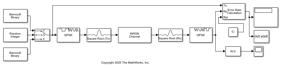
The cm_varsize_qpsk_ber.slx model generates frames of source data by using two Bernoulli Binary blocks. One Bernoulli Binary block outputs 2000 samples per frame and the other outputs 4000 samples per frame. The model uses a switch to randomly vary which Bernoulli Binary block supplies the frame of source data to transmit. The model plots the frame length variation and computes the BER for each input frame.
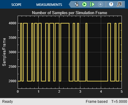
Print the number of samples per frame and the BER for several frames. The BER varies from frame to frame due to the random input data and small number of samples per frame.
Frame #  Samples/Frame  BER
  141      4000          0.0003
  142      4000          0.0013
  143      2000          0.0000
  144      2000          0.0020
  145      2000          0.0010
  146      2000          0.0000
  147      4000          0.0022
  148      4000          0.0008
  149      4000          0.0013
  150      4000          0.0010
  151      2000          0.0035
Variable-Size Signals in Code
Functions in Communications Toolbox inherently support variable-size input signals. Additionally many System objects also support variable-size input signals. In these System objects, you can change the frame size (number of rows) of the input matrix even when the object is locked. The number of channels (number of columns) of the input matrix must remain constant. The System object™ locks when you call the object to run its algorithm. For System objects that do not support variable-size input signals, you must unlock the object to change the frame size.
These tables list System objects in Communications Toolbox that support variable-size signals.
![]() Error Detection and Correction
Error Detection and Correction
Vary Signal Length While Computing GMSK Error Rate in MATLAB
This example varies the input signal length from frame to frame while computing the bit error rate (BER) for each frame in a GMSK-modulated link level simulation.
The System objects used in the simulation support variable-size input signals. For the error rate calculator, account for the delay between the modulator and demodulator, caused by the Viterbi algorithm.
s = rng(2025); % Set rng for repeatability
gmskmodulator = comm.GMSKModulator( ...
    BitInput=true, ...
    InitialPhaseOffset=pi/4);
gmskdemodulator = comm.GMSKDemodulator( ...
    BitOutput=true, ...
    InitialPhaseOffset=pi/4);
errorRate = comm.ErrorRate( ...
    ReceiveDelay=gmskdemodulator.TracebackDepth);
In a for loop, run multiple frames of the simulation computing the error rate for each simulation frame. The frame size increases for each subsequent loop iteration.
snr = 0;
numSamp = 1e6;
buf = randi([0 1],numSamp,1);

for k=1:5
    numSamp = k*1e5;
    data = buf(1:numSamp,1);
    modSignal = gmskmodulator(data);
    noisySignal = awgn(modSignal,snr);
    receivedData = gmskdemodulator(noisySignal);
    errorStats = errorRate(data,receivedData);
Display the error statistics. The BER stabilizes as the number of samples per frame increases.
    fprintf('Frame # %d\n',k)
    fprintf(['Error rate = %f\nNumber of errors = %d' ...
        '\nNumber of samples = %d\n'], ...
        errorStats(1),errorStats(2),errorStats(3))
end
Frame # 1
Error rate = 0.000040
Number of errors = 4
Number of samples = 99984
Frame # 2
Error rate = 0.000087
Number of errors = 26
Number of samples = 299984
Frame # 3
Error rate = 0.000087
Number of errors = 52
Number of samples = 599984
Frame # 4
Error rate = 0.000094
Number of errors = 94
Number of samples = 999984
Frame # 5
Error rate = 0.000097
Number of errors = 146
Number of samples = 1499984