Allpass Filter
Single-section or multiple-section allpass filter
Libraries:
DSP System Toolbox /
Filtering /
Filter Implementations
Description
The Allpass Filter block filters each channel of the input signal independently using a single-section or multiple-section (cascaded) allpass filter. You can implement the allpass filter using a minimum multiplier, wave digital filter, or a lattice structure.
In minimum multiplier form, the block uses the minimum number of required multipliers, n, with 2n delay units and 2n adders. In wave digital filter form, the block uses only n multipliers and n delay units, at the expense of 3n adders. The lattice structure uses 2n multipliers, n delay units, and 2n adders. For more details on these structures, see Algorithms.
Ports
Input
Output
Parameters
If a parameter is listed as tunable, then you can change its value during simulation.
Minimum multiplier— This structure uses the minimum number of required multipliers, n, with 2n delay units and 2n adders. The coefficients to this structure are specified through the Allpass polynomial coefficients parameter.Wave Digital Filter— The structure uses n multipliers and n delay units, at the expense of 3n adders. The coefficients to this structure are specified through the Wave Digital Filter allpass coefficients parameter.Lattice— The structure uses 2n multipliers, n delay units, and 2n adders. The coefficients to this structure are specified through the Lattice allpass coefficients parameter.
For more details on these structures, see Algorithms.
When you select this check box and set Internal allpass
structure to Minimum multiplier,
the allpass polynomial coefficients are input through the
coeffs port. When you clear this check box, the
allpass polynomial coefficients are specified on the block dialog through
the Allpass polynomial coefficients parameter.
When you select this check box and set Internal allpass
structure to Lattice, the lattice
allpass coefficients are input through the coeffs port.
When you clear this check box, the lattice allpass coefficients are
specified on the block dialog through the Lattice allpass
coefficients parameter.
Dependencies
To enable this parameter, set Internal allpass
structure to Minimum
multiplier or
Lattice.
Specify the real allpass polynomial filter coefficients in minimum multiplier form as an N-by-1 matrix, N-by-2 matrix, or an N-by-4 matrix.
N-by-1 matrix — The block realizes N first-order allpass sections.
N-by-2 matrix — The block realizes N second-order allpass sections.
N-by-4 matrix — The block realizes N fourth-order allpass sections. (since R2024a)
The default value [-2^(-1/2), 1/2] defines a stable
second-order allpass filter with poles and zeros at ±π/3 in the
z-plane.
Tunable: Yes
Dependencies
To enable this parameter, set Internal allpass
structure to Minimum
multiplier and clear the Specify
coefficients from input port parameter.
Specify the real allpass filter coefficients in wave digital filter form.
The coefficients can be N-by-1 matrix for
N first-order allpass sections and
N-by-2 matrix for N second-order
allpass sections. The default value, [1/2, -2^(1/2)/3],
is a transformed version of the default value of allpass polynomial
coefficients. This value is computed using allpass2wdf(Allpass
polynomial coefficients). These coefficients define the same
stable second-order allpass filter as when the allpass structure is set to
Minimum multiplier.
Tunable: Yes
Dependencies
To enable this parameter, set Internal allpass
structure to Wave Digital
Filter.
on— When you set select this check box, the last section is considered first order. Also, the second element of the last row of the N-by-2 matrix is ignored. In case of the minimum multiplier structure, if you specify an N-by-4 matrix, this parameter has no effect on the filter coefficients.off— When you do not select this check box, the last section is considered second-order.
Dependencies
To enable this parameter, set Internal allpass
structure to Minimum
multiplier or Wave Digital
Filter.
Specify the real or complex allpass coefficients as lattice reflection
coefficients. The default value, [-2^(1/2)/3, 1/2], is a
transformed and transposed version of the default value of the allpass
polynomial coefficients. This value is computed using
transpose(tf2latc(1, [1 A])), where
A is the value specified in Allpass
polynomial coefficients.
Tunable: Yes
Dependencies
To enable this parameter, set Internal allpass
structure to Lattice and clear
the Specify coefficients from input port
parameter.
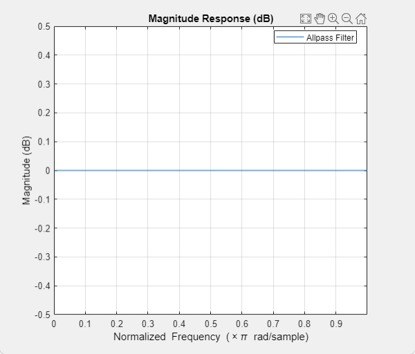
Opens the Filter Visualization Tool, fvtool, and
displays the magnitude response of the allpass filter. The response is based
on the parameters. Changes made to these parameters update
fvtool.
To update the magnitude response while fvtool is
running, modify the block parameters and click
Apply.
To view the magnitude response and phase response simultaneously, click the Magnitude and Phase responses button on the toolbar.
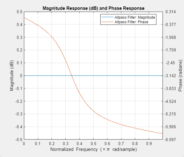
In this example, the magnitude response is flat and the phase response varies with frequencies. This varying phase response has applications in phase equalization, notch filtering, and multirate filtering. You can realize a lowpass filter using a parallel combination of two allpass filters that have 180 degrees of phase shift with respect to each other.
Specify the type of simulation to run. You can set this parameter to:
Interpreted execution— Simulate model using the MATLAB® interpreter. This option shortens startup time.Code generation— Simulate model using generated C code. The first time you run a simulation, Simulink® generates C code for the block. The C code is reused for subsequent simulations as long as the model does not change. This option requires additional startup time but provides faster subsequent simulations.
Block Characteristics
Data Types |
|
Multidimensional Signals |
|
Variable-Size Signals |
|
Algorithms
The transfer function of an allpass filter is given by
.
c is allpass polynomial coefficients vector. The order, n, of the transfer function is the length of vector c.
In the minimum multiplier form and wave digital form, the allpass filter is implemented as a cascade of either second-order (biquad) sections or first-order sections. When the coefficients are specified as an N-by-2 matrix, each row of the matrix specifies the coefficients of a second-order filter. The last element of the last row can be ignored based on the trailing first-order setting. When the coefficients are specified as an N-by-1 matrix, each element in the matrix specifies the coefficient of a first-order filter. The cascade of all the filter sections forms the allpass filter.
In the lattice form, the coefficients are specified as a vector.
These structures are computationally more economical and structurally more stable compared to the generic IIR filters, such as df1, df1t, df2, df2t. For all structures, the allpass filter can be a single-section or a multiple-section (cascaded) filter. The different sections can have different orders, but they are all implemented according to the same structure.
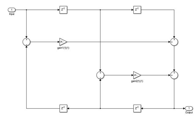
This structure realizes the allpass filter with the minimum number of required multipliers,
equal to the order n. It also uses 2n delay units
and 2n adders. The multipliers uses the specified coefficients, which
are equal to the polynomial vector c in the allpass transfer
function.
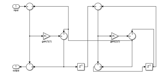
In this second-order section of the minimum multiplier structure, the coefficients
vector, c, is equal to [0.1 -0.7].
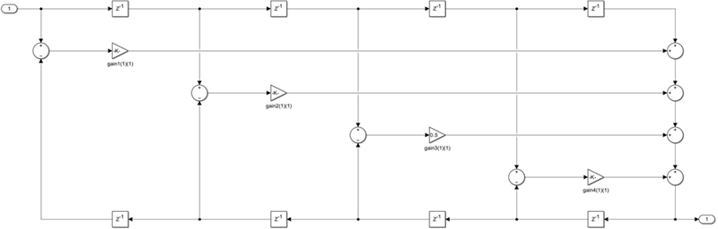
In this fourth-order section of the minimum multiplier structure, the coefficients
vector, c, is equal to [-0.7071 0.5 0.4
0.25].
This structure uses n multipliers, but only n delay
units, at the expense of requiring 3n adders. To
use this structure, specify the coefficients in wave digital filter
(WDF) form. Obtain the WDF equivalent of the conventional allpass
coefficients using allpass2wdf(allpass_coefficients).
To convert WDF coefficients into the equivalent allpass polynomial
form, use wdf2allpass(WDF coefficients). In this
second-order section of the WDF structure, the coefficients vector w is
equal to allpass2wdf([0.1 -0.7]).
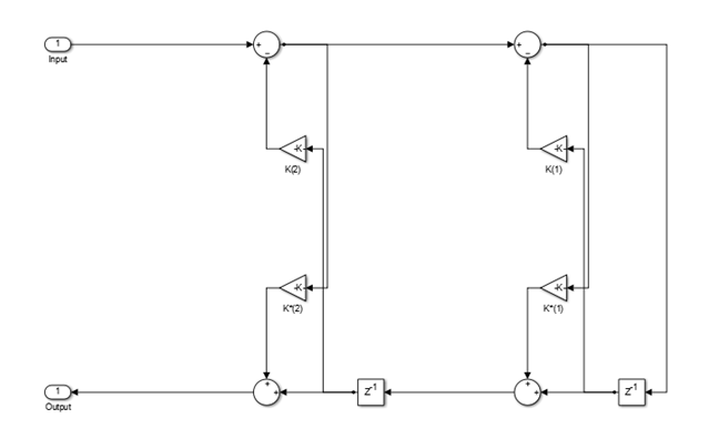
This lattice structure uses 2n multipliers, n delay
units, and 2n adders. To use this structure, specify
the coefficients as a vector.
You can obtain the lattice equivalent of the conventional allpass
coefficients using transpose(tf2latc(1, [1 allpass_coefficients])).
In the following second-order section of the lattice structure, the
coefficients vector is computed using transpose(tf2latc(1,
[1 0.1 -0.7])). Use these coefficients for a filter that
is functionally equivalent to the minimum multiplier structure with
coefficients [0.1 -0.7].
References
[1] Regalia, Philip A., Sanjit K. Mitra, and P.P.Vaidyanathan. “The Digital All-Pass Filter: A Versatile Signal Processing Building Block.” Proceedings of the IEEE. 76, no. 1 (1988): 19–37.
[2] Lutovac, M., D. Tosic, and B. Evans. Filter Design for Signal Processing Using MATLAB and Mathematica. Upper Saddle River, NJ: Prentice Hall, 2001.