Verify Generated Code Using HDL Test Bench at Command Line
This example shows how to generate a HDL test bench and verify the generated code for your design. The example assumes that you have already generated HDL code for your model. If you haven't already generated HDL code, you can still open this model and generate the HDL test bench. Before generating the test bench, HDL Coder™ runs code generation to make sure that there is at least one successful code generation run before generating the testbench.
This example illustrates how to verify the generated code for the FIR filter model. To learn how to generate HDL code, see Generate HDL Code from Simulink Model from Command Line.
FIR Filter Model
This example uses the Symmetric FIR filter model that is compatible for HDL code generation. To open this model at the command line, enter:
sfir_fixed
The model uses a division of labor that is suitable for HDL design.
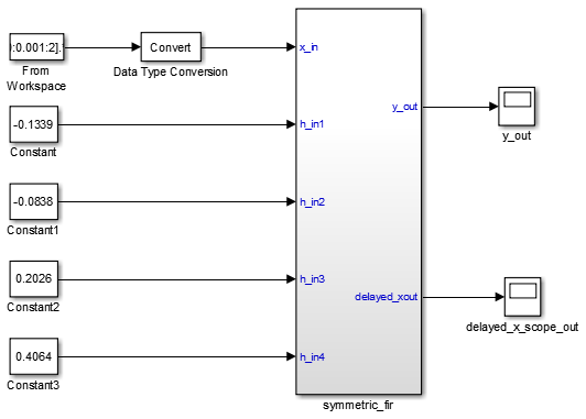
The
symmetric_firsubsystem, which implements the filter algorithm, is the device under test (DUT). An HDL entity is generated from this subsystem.The top-level model components that drive the subsystem work as a test bench.
The top-level model generates 16-bit
fixed-point input signals for the
symmetric_fir subsystem. The
Signal From Workspace block generates a test input
(stimulus) signal for the filter. The four
Constant blocks provide filter
coefficients. The Scope blocks are used for
simulation and are not used for HDL code generation.
To navigate to the symmetric_fir subsystem,
enter:
open_system('sfir_fixed/symmetric_fir')
Create a Folder and Copy Relevant Files
In MATLAB®:
Create a folder named
sl_hdlcoder_work, for example:mkdir C:\work\sl_hdlcoder_worksl_hdlcoder_workstores a local copy of the example model and folders and generated HDL code. Use a folder location that is not within the MATLAB folder tree.Make the
sl_hdlcoder_workfolder your working folder, for example:cd C:\work\sl_hdlcoder_workSave a local copy of the
sfir_fixedmodel to your current working folder. Leave the model open.
What is a HDL Test Bench?
To verify the functionality of the HDL code that you generated for the DUT, generate a HDL test bench. A test bench includes:
Stimulus data generated by signal sources connected to the entity under test.
Output data generated by the entity under test. During a test bench run, this data is compared to the outputs of the VHDL® code, for verification purposes.
Clock, reset, and clock enable inputs to drive the entity under test.
A component instantiation of the entity under test.
Code to drive the entity under test and compare its outputs to the expected data.
You can simulate the generated test bench and script files with the Siemens® ModelSim™ simulator.
How to Verify the Generated Code
This example illustrates how to generate a HDL test bench to simulate and verify the generated HDL code for your design. You can also verify the generated HDL code from your model using these methods:
| Verification Method | For More Information |
|---|---|
| Validation Model | Generated Model and Validation Model |
| HDL Cosimulation (requires HDL Verifier™) | Cosimulation |
| SystemVerilog DPI Test Bench (requires HDL Verifier) | SystemVerilog DPI Test Bench |
| FPGA-in-the-Loop (requires HDL Verifier) | FPGA-in-the-Loop |
Generate HDL Test Bench
Depending on whether you generated VHDL, Verilog® or SystemVerilog code, generate VHDL, Verilog or SystemVerilog test bench code. The test bench code drives
the HDL code that you generated for the DUT. By default, the
HDL code and the test bench code are written to the same
target folder hdlsrc relative to the
current folder.
To generate test bench code and the scripts for compilation and
simulation, use the makehdltb function. At the command
line,
enter:
makehdltb('sfir_fixed/symmetric_fir')
To specify the customizations before you generate testbench
code, use the hdlset_param function. You can also
specify various name-value pair arguments with the
makehdltb function to
customize HDL code generation options while generating HDL
code. For example, to generate Verilog test bench code, use
the TargetLanguage
property.
makehdltb('sfir_fixed/symmetric_fir', 'TargetLanguage', 'Verilog')
hdlset_param, set this
parameter on the model and then run the
makehdltb
function.hdlset_param('sfir_fixed', 'TargetLanguage', 'Verilog') makehdltb('sfir_fixed/symmetric_fir')
If you haven't already generated code for your model, HDL Coder compiles the model and generates HDL code before generating the test bench. Depending on model display options such as port data types, the model can change in appearance after code generation.
As test bench generation proceeds, HDL Coder displays progress messages. The process should complete with the message
### HDL TestBench Generation Complete.
After generating the test bench, you see the generated files in
the hdlsrc folder.
View HDL Test Bench Files
symmetric_fir_tb.vhd: VHDL test bench code, with generated test and output data. If you generated Verilog or SystemVerilog test bench code, the generated files aresymmetric_fir_tb.vorsymmetric_fir_tb.sv.symmetric_fir_tb_pkg.vhd: Package file for VHDL test bench code. If you generated SystemVerilog test bench code, the generated file issymmetric_fir_tb_pkg.sv. This file is not generated if you specified Verilog as the target language.symmetric_fir_tb_compile.vhd: Compilation script (vcomcommands). This script compiles and loads the entity to be tested (symmetric_fir.vhd) and the test bench code (symmetric_fir_tb.vhd).symmetric_fir_tb_sim.do: Siemens ModelSim script to initialize the simulator, set up wave window signal displays, and run a simulation.
To view the generated test bench code in the MATLAB Editor, double-click the
symmetric_fir_tb.vhd,
symmetric_fir_tb.v or
symmetric_fir_tb.sv file in the
current folder.
Run Simulation and Verify Generated HDL Code
To verify the simulation results, you can use the Siemens ModelSim simulator. Make sure that you have already installed Siemens ModelSim.
To launch the simulator, use the vsim (HDL Verifier) function. This
command shows how to open the simulator by specifying the
path to the
executable:
vsim('vsimdir','C:\Program Files\ModelSim\questasim\10.6b\win64\vsim.exe')
To compile and run a simulation of the generated model and test
bench code, use the scripts that are generated by
HDL Coder. Following example illustrates the commands
that compile and simulate the generated test bench for the
sfir_fixed/symmetric_fir
subsystem.
Open the Siemens ModelSim software and navigate to the folder that has the previously generated code files and the scripts.
QuestaSim>cd C:/work/sl_hdlcoder_work/hdlsrc
Use the generated compilation script to compile and load the generated model and text bench code. Run this command to compile the generated code.
QuestaSim>do symmetric_fir_tb_compile.do
Use the generated simulation script to execute the simulation. The following listing shows the command and responses. You can ignore any warning messages. The test bench termination message indicates that the simulation has run to completion without comparison errors. Run this command to simulate the generated code.
QuestaSim>do symmetric_fir_tb_sim.do
The simulator optimizes your design and displays the results of simulating your HDL design in a wave window. if you don't see the simulation results, open the wave window. The simulation script displays inputs and outputs in the model including the clock , reset, and clock enable signals in the wave window.

You can now view the signals and verify that the simulation results match the functionality of your original design. After verifying, close the Siemens ModelSim simulator, and then close the files that you have opened in the MATLAB Editor.
See Also
Functions
Model Settings
- HDL test bench | Cosimulation model | SystemVerilog DPI test bench | Simulation tool | HDL code coverage