Curb Detection and Tracking in 3-D Lidar Point Cloud
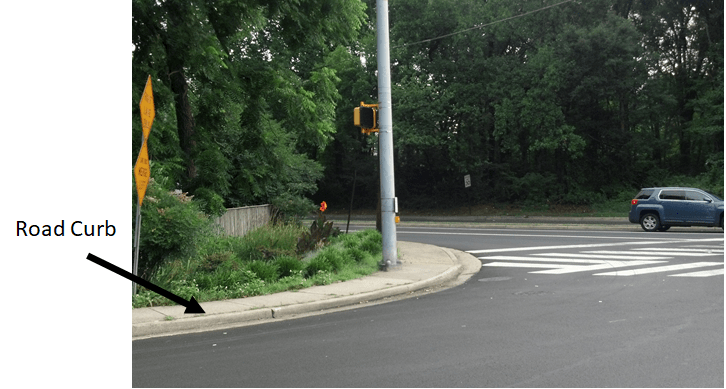
This example shows how to detect and track curbs in lidar point clouds. A curb is a line of stone or concrete, that connects the roadway to the sidewalk. Curbs act as delimiters for the drivable area of the road.
In the absence of GPS signals, detecting the curb position is important for path planning and safe navigation in autonomous driving applications.
This example uses a subset of the PandaSet data set from Hesai and Scale. The PandaSet contains lidar point cloud scans of various city scenes captured using the Pandar64 sensor.
Introduction
Curb detection in lidar point cloud involves the detecting the left and right curbs of a road with respect to the ego vehicle. The lidar sensor is mounted on the top of the vehicle.
Use these steps to detect curbs in the point cloud data captured by the lidar sensor:
Extract a region of interest(ROI)
Classify on-road and off-road points
Identify the road angles using the off-road points
Detect candidate curb points using the on-road points
Download Lidar Data Set
The size of the data set is 109 MB, and it contains 50 preprocessed organized point clouds. Each point cloud is specified as a 64-by-1856-by-3 array. The ground truth data contains the semantic segmentation labels for 13 classes. The point clouds are stored in PCD format, and the ground truth data is stored in PNG format.
Download the PandaSet data set using the helperDownloadPandasetData helper function, defined at the end of this example.
% Set random seed to generate reproducible results
rng("default");
[ptCloudData,labelsData] = helperDownloadPandasetData;
Select the first frame of the data set for further processing. Visualize the point cloud.
ptCloud = ptCloudData{1};
labels = labelsData{1};

% Visualize the input point cloud with corresponding ground truth labels
figure
pcshow(ptCloud.Location,labels)
axis on
view(2)
title("Input Lidar Point Cloud")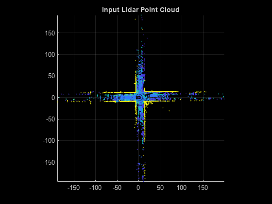
Preprocess Data
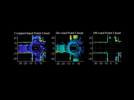
As a preprocessing step for detecting curb points, first extract a region of interest from the point cloud and classify the points within it as on-road or off-road points.
Based on the installed position of the lidar sensor, the point cloud data is sparse beyond a certain distance. To ensure the point cloud you extract is dense enough for further processing, specify an ROI within a limited distance of the sensor.
% Define ROI in meters
xLim = [-35 20];
yLim = [-25 25];

roiIdx = ptCloud.Location(:,:,1) >= xLim(1) & ...
    ptCloud.Location(:,:,1) <= xLim(2) & ...
    ptCloud.Location(:,:,2) >= yLim(1) & ...
    ptCloud.Location(:,:,2) <= yLim(2);
Classify the point cloud into on-road and off-road points using these labels:
1 — Unlabeled
2 — Vegetation
3 — Ground
4 — Road
5 — Road Marking
6 —Side Walk
7 — Car
8 — Truck
9 — Other Vehicle
10 — Pedestrian
11 — Road Barrier
12 — Signs
13 — Buildings
labels(~roiIdx) = nan;
% The on-road points consist of ground, road and sidewalk
onRoadLabelsIdx = (labels == 3 | labels == 4 | labels == 6);

% The off-road points consist of buildings and other objects
offRoadLabelsIdx = (labels == 2 | labels == 11 | ...
    labels == 12 | labels == 13);

% Visualize the point cloud, along with on-road and off-road points.
figure
subplot(1,3,1)
pcshow(select(ptCloud,roiIdx))
axis on
view(2)
title("Cropped Input Point Cloud")

subplot(1,3,2)
pcshow(select(ptCloud,onRoadLabelsIdx))
axis on
view(2)
title("On-road Point Cloud")

subplot(1,3,3)
pcshow(select(ptCloud,offRoadLabelsIdx))
axis on
view(2)
title("Off-road Point Cloud")
If semantic labels are not available with your data set, you can compute them using a deep learning network. For more information, see the Lidar Point Cloud Semantic Segmentation Using SqueezeSegV2 Deep Learning Network example.
Detect Road Shape
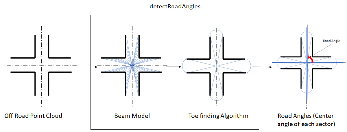
Use the detectRoadAngles function to detect the road angles in the off-road point cloud.
The function applies the beam model to the off-road points. For more information about the beam model, see [1] and [2].
Then, it applies a customized version of the toe-finding algorithm [3] to the normalized beam lengths to find the road angles.
% Select the off-road point cloud
offRoadPtCloud = select(ptCloud,offRoadLabelsIdx);

% Use the detectRoadAngles function to detect the road angles
roadAngles = detectRoadAngles(offRoadPtCloud);
Detect Road Curbs
Use the segmentCurbPoints function to segment the curb points from the on-road point cloud. The function uses the following steps to compute the curb points:
1) Extract the feature curb points from the on-road points.
To identify the curb points in the on-road point cloud, following spatial features are used to model the road curb:
Smoothness Feature [2] — This feature checks for the smoothness of the area around a point. A higher smoothness value indicates that the point is an edge point, and a lower values indicates that the point is a plane point.
Height Difference Feature [2] — This feature checks for the standard deviation and the maximum difference of height around a point.
Horizontal and Vertical Continuity Feature [1] — This feature checks for the horizontal and vertical continuity of a point with respect to its immediate neighboring points.
The function computes these features for every point in each scan line. The points which satisfy the feature thresholds for the above features are the feature curb points.
2) Compute the candidate curb points from the feature curb points.
The feature curb points may contain false positives. To remove the false positives, the function further processes the feature curb points using RANSAC based quadratic polynomial fitting to extract the candidate curb points.
% Select the off-road point cloud
onRoadPtCloud = select(ptCloud,onRoadLabelsIdx,OutputSize='full');

% Use the segmentCurbPoints function to segment the curbs in the on-road point cloud
[~,candidateCurbPoints] = segmentCurbPoints(onRoadPtCloud,roadAngles, ...
    HorizontalAngularResolution=0.24);

% Visualize the point cloud overlaid with the candidate curb points
figure
pcshow(select(ptCloud,roiIdx).Location,"w")
view(2)
hold on
pcshow(candidateCurbPoints.Location,"r",MarkerSize=200)
view(2)
hold off
axis on
title("Candidate Curb Points Detected")

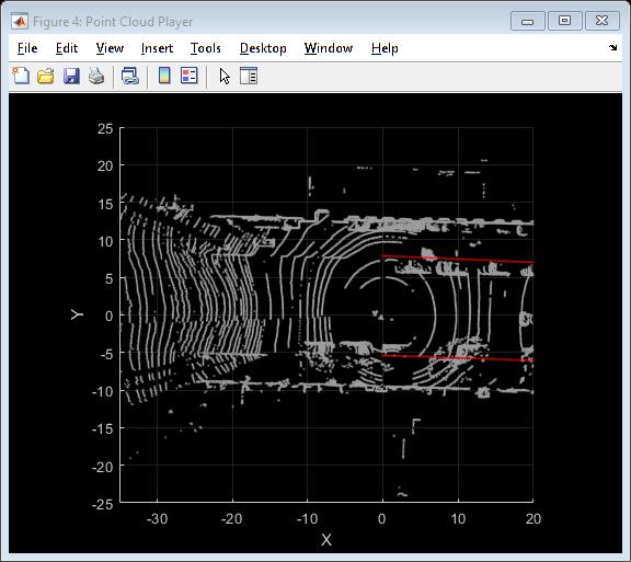
Track Curb Points
Loop through and process the lidar data to extract and track the candidate curb points. Tracking curb points improves the robustness of curb detection. You can halt the curb tracking at the segmented roads, and restart it when the ego vehicle leaves the segmented roads. Curb tracking involves polynomial fitting on the XY-points using a 2-degree polynomial represented as , where a, b, and c are the polynomial parameters. Curb tracking is a two-step process:
Track curb polynomial parameters a and b to control the curvature of the polynomial.
Track curb polynomial parameter c to control the drift of the polynomial.
Update these parameters by using a Kalman filter with a constant velocity motion model. Use the configureKalmanFilter function to initialize a Kalman filter.
rng('default')
player = pcplayer([-35 20],[-25 25],[-10 10],MarkerSize=6);

candidateCurbQueue = [];
candidateCurbQueueSize = 3;
candidateCurbQueueCount = 1;
prevOffRoadPtCloud = [];
prevCandidateCurbPoints = [];
prevAngle = [];
rmse = 1;

% Initial values for Kalman filter
initParams.initialEstimateError = [1 1 1]*1e-1;
initParams.motionNoise = [1 1 1]*1e-7;
initParams.measurementNoise = 1e3;

leftTracker.drift = [];
leftTracker.filteredDrift = [];
leftTracker.curveSmoothness = [];
leftTracker.filteredCurveSmoothness = [];

rightTracker.drift = [];
rightTracker.filteredDrift = [];
rightTracker.curveSmoothness = [];
rightTracker.filteredCurveSmoothness = [];

isTracking = false;
isLeftCurbTrackingInitialised = false;
isRightCurbTrackingInitialised = false;

% Find the points lying within ROI
xLim = [-35 20];
yLim = [-25 25];

[ptCloudData,labelsData] = helperDownloadPandasetData;
for fileIdx = 1:numel(ptCloudData)
    % Load the point cloud and its ground truth labels
    ptCloud = ptCloudData{fileIdx};
    labels = labelsData{fileIdx};

    % Find the points lying within ROI
    roiIdx = ptCloud.Location(:,:,1) >= xLim(1) & ...
        ptCloud.Location(:,:,1) <= xLim(2) & ...
        ptCloud.Location(:,:,2) >= yLim(1) & ...
        ptCloud.Location(:,:,2) <= yLim(2);

    labels(~roiIdx) = nan;

    % Classify the points into on-road points and off-road points
    onRoadLabelsIdx = (labels == 3| labels == 4 | labels == 6);
    offRoadLabelsIdx = (labels == 2 | labels == 11 | labels == 12 | ...
        labels == 13);
    offRoadPtCloud = select(ptCloud,offRoadLabelsIdx);
    onRoadPtCloud = select(ptCloud,onRoadLabelsIdx,'OutputSize','full');

    % Compute the road angles using off-road points
    roadAngles = detectRoadAngles(offRoadPtCloud);

    % Compute number of road segments in front and behind the
    % ego vehicle
    numFrontRoadSegments = sum(roadAngles < 110 | roadAngles > 250);
    numRearRoadSegments = sum(~(roadAngles < 110 | roadAngles > 250));

    % Check if curb tracking should be enabled or disabled
    if ~isTracking
        if (numFrontRoadSegments < numRearRoadSegments) || ...
                (numel(roadAngles) == 2)
            isTracking = true;
        end
    else
        if numFrontRoadSegments > numRearRoadSegments
            isTracking = false;
            isLeftCurbTrackingInitialised = false;
            isRightCurbTrackingInitialised = false;
        end
    end

    % Transform the candidate points from the previous frames to the
    % current frame
    if ~isempty(prevOffRoadPtCloud)
        gridStep = 0.5;
        [tform,rmse] = pcregistericp(prevOffRoadPtCloud,offRoadPtCloud);
        prevCandidateCurbPoints = pctransform(pccat(candidateCurbQueue), ...
            tform);
    end

    % Compute the curb points using the on-road points
    if rmse > 0.7
        [~,candidateCurbPoints] = segmentCurbPoints(onRoadPtCloud, ...
            roadAngles,HorizontalAngularResolution=0.24);
    else
        [~,candidateCurbPoints] = segmentCurbPoints(onRoadPtCloud, ...
            roadAngles,prevCandidateCurbPoints, ...
            HorizontalAngularResolution=0.24);
    end

    if isempty(candidateCurbPoints)
        prevOffRoadPtCloud = offRoadPtCloud;
        prevAngle = roadAngles;
        continue;
    end

    curbPoints = candidateCurbPoints.Location;
    xVal = linspace(0,xLim(2),80);
    if isTracking
        leftCurb = [];
        rightCurb = [];

        model = pcfitplane(select(ptCloud,onRoadLabelsIdx),0.1, ...
            [0 0 1]);
        modelParams = model.Parameters;

        candidateAngles = atan2d(curbPoints(:,2), curbPoints(:,1));
        candidateAngles(candidateAngles < 0) = candidateAngles( ...
            candidateAngles < 0) + 360;

        % Divide the candidate curb points, into left and right curb points
        if (roadAngles(1) >= 270 || roadAngles(1) < 90) && ...
                (roadAngles(2) >= 90 && roadAngles(2) < 270)
            idx = candidateAngles >= roadAngles(1) & ...
                candidateAngles < roadAngles(2);
        else
            idx = candidateAngles >= roadAngles(2) | ...
                candidateAngles < roadAngles(1);
        end
        leftCandidateCurbPoints = curbPoints(idx,:);
        rightCandidateCurbPoints = curbPoints(~idx,:);

        % Compute polynomials to track left and right curbs
        leftPolynomial = fitPolynomialRANSAC( ...
            leftCandidateCurbPoints(:,1:2),2,0.1);
        rightPolynomial = fitPolynomialRANSAC( ...
            rightCandidateCurbPoints(:,1:2),2,0.1);

        if ~isempty(leftPolynomial)
            if ~isLeftCurbTrackingInitialised
                [leftFilter,leftCurb] = helperTrackCandidateCurbs( ...
                    leftPolynomial,xVal,modelParams,initParams);
                isLeftCurbTrackingInitialised = true;
            else
                [leftPolynomial,leftCurb,leftTracker] = helperTrackCandidateCurbs( ...
                    leftPolynomial,xVal,modelParams, ...
                    leftFilter,leftTracker);
            end
        end
        if ~isempty(rightPolynomial)
            if ~isRightCurbTrackingInitialised
                [rightFilter,rightCurb] = helperTrackCandidateCurbs( ...
                    rightPolynomial,xVal,modelParams,initParams);
                isRightCurbTrackingInitialised = true;
            else
                [rightPolynomial,rightCurb,rightTracker] = helperTrackCandidateCurbs( ...
                    rightPolynomial,xVal,modelParams, ...
                    rightFilter,rightTracker);
            end
        end
        ptCloud = select(ptCloud,roiIdx);

        % Use the helperVisualiseOutput helper function, attached to this
        % example as a supporting file to visualize the final output
        outputPtCloud = helperVisualiseOutput(ptCloud,leftCurb,rightCurb, ...
            []);
    else
        ptCloud = select(ptCloud,roiIdx);

        % Use the helperVisualiseOutput helper function, attached to this
        % example as a supporting file to visualize the final output
        outputPtCloud = helperVisualiseOutput(ptCloud,curbPoints);
    end

    candidateCurbQueue = [candidateCurbQueue;candidateCurbPoints];
    if candidateCurbQueueCount <= candidateCurbQueueSize
        candidateCurbQueueCount = candidateCurbQueueCount + 1;
    else
        candidateCurbQueue = candidateCurbQueue(2:end);
    end

    prevOffRoadPtCloud = offRoadPtCloud;
    prevAngle = roadAngles;
    if isOpen(player)
        view(player,outputPtCloud);
        view(player.Axes,[0 90])
        camva(player.Axes,0)
    end
end
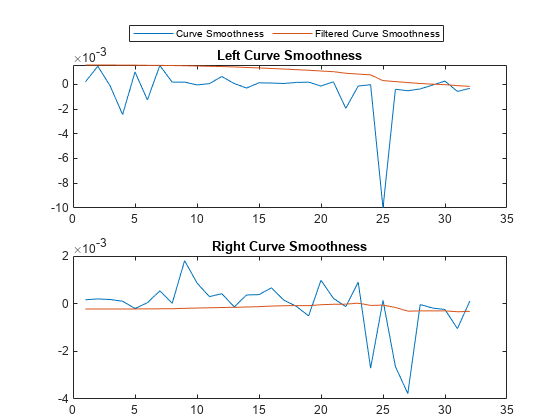
Analyze Drift and Smoothness of Curb Tracking
To analyze the curb detection results, compare them against the tracked curb polynomials by plotting them in figures. Each plot compares the parameters with and without the Kalman filter. The first figure compares the drift of curbs along the y-axis, and the second figure compares the smoothness of the curb polynomials. Smoothness is the rate of change of the curb polynomial slope.
figure
ax = subplot(2,1,1);
plot(leftTracker.drift)
hold on
plot(leftTracker.filteredDrift)
hold off
title("Left Curb Drift Along Y-axis")
ax.Position(2) = ax.Position(2) - 0.08;
ax = subplot(2,1,2);
plot(rightTracker.drift)
hold on
plot(rightTracker.filteredDrift)
hold off
title("Right Curb Drift Along Y-axis")
ax.Position(2) = ax.Position(2) - 0.06;
Lgnd = legend("Drift Values","Filtered Drift Values", ...
    "Orientation","Horizontal");
Lgnd.Position(1:2) = [0.29 0.9];

figure
ax = subplot(2,1,1);
plot(leftTracker.curveSmoothness);
hold on
plot(leftTracker.filteredCurveSmoothness)
hold off
title("Left Curve Smoothness")
ax.Position(2) = ax.Position(2) - 0.08;
ax = subplot(2,1,2);
plot(rightTracker.curveSmoothness);
hold on
plot(rightTracker.filteredCurveSmoothness)
hold off
title("Right Curve Smoothness")
ax.Position(2) = ax.Position(2) - 0.06;
Lgnd = legend("Curve Smoothness","Filtered Curve Smoothness", ...
    "Orientation","Horizontal");
Lgnd.Position(1:2) = [0.23 0.9];
Helper Functions
The helperDownloadPandasetData helper function loads the lidar data set into the MATLAB® workspace.
function [ptCloudData,labelsData] = helperDownloadPandasetData()
lidarDataTarFile = matlab.internal.examples.downloadSupportFile('lidar', ...
    'data/CurbPointCloudData.tar');
filepath = fileparts(lidarDataTarFile);
outputFolder = fullfile(filepath,'CurbPointCloudData');

% Check if tar file is downloaded, but not uncompressed.
if (~exist(fullfile(outputFolder,"Lidar"),"file")) ...
        &&(~exist(fullfile(outputFolder,"semanticLabels"),"file"))
    untar(lidarDataTarFile,outputFolder);
end

lidarFiles =  dir(fullfile(outputFolder,'Lidar','*.pcd'));
labelFiles = dir(fullfile(outputFolder,'semanticLabels','*.png'));

ptCloudData = cell(numel(lidarFiles),1);
labelsData = cell(numel(labelFiles),1);

for fileIdx = 1:numel(lidarFiles)
    ptCloud = pcread(fullfile(lidarFiles(fileIdx).folder,lidarFiles(fileIdx).name));
    % The example follows the convention that ego vehicle motion is along
    % the positive x-axis, hence, transform the point cloud
    theta = -90;
    trans = [0 0 0];
    tform = rigidtform3d([0 0 theta],trans);
    ptCloudData{fileIdx} = pctransform(ptCloud,tform);
    labelsData{fileIdx} = imread(fullfile(labelFiles(fileIdx).folder,labelFiles(fileIdx).name));
end
end
The helperTrackCandidateCurbs helper function tracks the candidate curb points using the Kalman filter.
function varargout = helperTrackCandidateCurbs(varargin)
polynomial = varargin{1};
xVal = varargin{2};
modelParams = varargin{3};
if numel(varargin) == 4
    initParams = varargin{4};
    initParams.initialEstimateError = initParams.initialEstimateError(1:2);
    initParams.motionNoise = initParams.motionNoise(1:2);
    curveInitialParameters = polynomial(1:2);
    driftInitialParameters = polynomial(3);

    % Configure Kalman filter
    filter.curveFilter = configureKalmanFilter( ...
        'ConstantVelocity',curveInitialParameters, ...
        initParams.initialEstimateError, ...
        initParams.motionNoise, ...
        initParams.measurementNoise);
    filter.driftFilter = configureKalmanFilter( ...
        'ConstantVelocity',driftInitialParameters, ...
        initParams.initialEstimateError, ...
        initParams.motionNoise, ...
        initParams.measurementNoise);

    varargout{1} = filter;
else
    filter = varargin{4};
    tracker = varargin{5};

    predict(filter.curveFilter);
    predict(filter.driftFilter);

    tracker.drift = [tracker.drift;polynomial(3)];
    tracker.curveSmoothness = [tracker.curveSmoothness;
        polynomial(1)];

    % Correct polynomial using Kalman filter
    updatedCurveParams = correct(filter.curveFilter, ...
        polynomial(1:2));
    updatedDriftParams = correct(filter.driftFilter, ...
        polynomial(3));

    % Update the polynomial
    polynomial = [updatedCurveParams,updatedDriftParams];
    tracker.filteredDrift = [tracker.filteredDrift;polynomial(3)];
    tracker.filteredCurveSmoothness = [tracker.filteredCurveSmoothness;
        polynomial(1)];
    varargout{1} = polynomial;
    varargout{3} = tracker;
end
% Y-coordinate estimation
yVal = polyval(polynomial,xVal);

% Z-coordinate estimation
zVal = (-modelParams(1)*xVal - modelParams(2)*yVal - modelParams(4)) ...
    /modelParams(3);

% Final Curb
curb = [xVal' yVal' zVal'];
varargout{2} = curb;
end
References
[1] Zhang, Yihuan, Jun Wang, Xiaonian Wang, and John M. Dolan. "Road-Segmentation-Based Curb Detection Method for Self-Driving via a 3D-LiDAR Sensor." IEEE Transactions on Intelligent Transportation Systems 19, no. 12 (December 2018): 3981–91. https://doi.org/10.1109/TITS.2018.2789462.
[2] Wang, Guojun, Jian Wu, Rui He, and Bin Tian. "Speed and Accuracy Tradeoff for LiDAR Data Based Road Boundary Detection." IEEE/CAA Journal of Automatica Sinica 8, no. 6 (June 2021): 1210–20. https://doi.org/10.1109/JAS.2020.1003414.
[3] Hu, Jiuxiang, Anshuman Razdan, John C. Femiani, Ming Cui, and Peter Wonka. "Road Network Extraction and Intersection Detection From Aerial Images by Tracking Road Footprints." IEEE Transactions on Geoscience and Remote Sensing 45, no. 12 (December 2007): 4144–57. https://doi.org/10.1109/TGRS.2007.906107.
[4] Hesai and Scale. PandaSet. Accessed September 18, 2025. https://pandaset.org/. The PandaSet data set is provided under the CC-BY-4.0 license.
[5] Xiao, Pengchuan, Zhenlei Shao, Steven Hao, et al. “PandaSet: Advanced Sensor Suite Dataset for Autonomous Driving.” 2021 IEEE International Intelligent Transportation Systems Conference (ITSC), IEEE, September 19, 2021, 3095–101. https://doi.org/10.1109/ITSC48978.2021.9565009.
See Also
detectRoadAngles | segmentCurbPoints | configureKalmanFilter