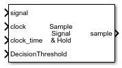
Signal Sampler
Libraries:
Mixed-Signal Blockset /
Utilities
Description
The Signal Sampler block estimates the value of an incoming fixed step discrete sampled signal at a specific time that is typically between two sample times. The block obtains this estimate using an accurate input value for the time and linear interpolation for the signal.
The Signal Sampler block calculates the time interval from the last sample to the exact time at which the clock transition occurred as the modular residue with respect to the sample interval. The block uses linear interpolation to calculate the new output sample value.
Ports
Input
Fixed step discrete input signal to be sampled, specified as a scalar.
Data Types: single | double | int8 | int16 | int32 | uint8 | uint16 | uint32 | fixed point
Saturated but sampled clock waveform, specified as a scalar. The input at the clock port, along with the input at the clock_time port, is used to define the time at which to sample the input signal.
Data Types: double
Exact time of the clock transition, specified as a scalar. The input at the clock_time port, along with the input at the clock port, is used to define the time at which to sample the input signal.
The voltage at which latched output switches polarity, specified as a scalar.
Data Types: double
Output
Sample output value at the clock edge, returned as a scalar.
The output has two modes:
Continuous — the output is exactly the value of the input signal at the time of the clock edge.
Latched — the output is binary, with values
-1or1.
Data Types: single | double | int8 | int16 | int32 | int64 | uint8 | uint16 | uint32 | uint64 | Boolean | fixed point
Parameters
Main
Determine when the input signal is sampled, either the rising or falling edge of the clock signal.
Programmatic Use
Block parameter:
ClockEdge |
| Type: character vector |
Values:
Rising| Falling |
Default:
Rising |
Determine the output sample mode, either Continuous or
Latched.
In Continuous mode, the output is exactly the value of
the input signal at the time of the clock edge.
In Latched mode, the output is binary, with values
-1 or 1.
Programmatic Use
Block parameter:
OutputMode |
| Type: character vector |
Values:
Continuous| Latched |
Default:
Continuous |
Select the simulation mode. This choice affects the simulation performance.
Simulating the model using the Code generation method
requires additional startup time, but the subsequent simulations run faster. Simulating
the model using the Interpreted execution method may reduce
the startup time, but the subsequent simulations run slower. For more information, see
Interpreted Execution vs. Code Generation.
Programmatic Use
Block parameter:
SimulateUsing |
| Type: character vector |
Values:
Code generation| Interpreted
execution |
Default:
Code generation |
Latched Output
Select to turn on the decision threshold port. When turned on, the voltage at the DecisionThreshold port is used to decide when to switch polarity for latched output. By default, this option is selected.
Decision threshold is supported as an AMI parameter.
Programmatic Use
Block parameter:
DecisionThresholdPort |
| Type: character vector |
| Values: on| off |
| Default: on |
The voltage at which latched output switches polarity, specified as a scalar. Use this parameter to define the decision threshold for latched output in the block itself.
Decision threshold is supported as an AMI parameter.
Dependencies
To enable this parameter, deselect the DecisionThresholdPort parameter.
Programmatic Use
Block parameter:
DecisionThreshold |
| Type: character vector |
| Values: scalar |
Default:
0 |
The voltage above or below the decision threshold needed to assure that the latched output switches to the correct polarity. This parameter is used to model the metastable region of the latch. The behavior is modeled as the worst case, in which the latched output remains unchanged unless the sampled voltage is outside the metastable region. If the data sample voltage lies within the region (±Latch sensitivity), there is a 50% probability of bit error.
Latch sensitivity is supported as an AMI parameter.
Programmatic Use
Block parameter:
Sensitivity |
| Type: character vector |
| Values: scalar |
Default:
0 |
Advanced
Time of a single symbol duration, specified as a real positive scalar in seconds.
Programmatic Use
Block parameter:
SymbolTime |
| Type: character vector |
| Values: real positive scalar |
Default:
100e-12 |
Data Types: double
Uniform time step of the waveform, specified as a real positive scalar in seconds.
Programmatic Use
Block parameter:
SampleInterval |
| Type: character vector |
| Values: real positive scalar |
Default:
6.25e-12 |
Data Types: double
Number of logic levels in the modulation scheme:
Select
2if the modulation scheme is NRZ(non-return to zero).Select
3if the modulation scheme PAM3 (pulse amplitude modulation level 3).Select
4if the modulation scheme PAM4 (pulse amplitude modulation level 4).
Programmatic Use
Block parameter:
Modulation |
| Type: character vector |
Values:
2.| 3 | 4 |
Default:
2 |
Data Types: char
Type of input waveform, either a sample by sample signal or an impulse response signal.
Programmatic Use
Block parameter:
WaveType |
| Type: character vector |
Values:
Sample.| Impulse |
Default:
Sample |
Version History
Introduced in R2022a
See Also
Clock Generator | CDR (SerDes Toolbox)
Topics
- Clock and Data Recovery in SerDes System (SerDes Toolbox)
- Model Clock Recovery Loops in SerDes Toolbox (SerDes Toolbox)
MATLAB Command
You clicked a link that corresponds to this MATLAB command:
Run the command by entering it in the MATLAB Command Window. Web browsers do not support MATLAB commands.
Seleziona un sito web
Seleziona un sito web per visualizzare contenuto tradotto dove disponibile e vedere eventi e offerte locali. In base alla tua area geografica, ti consigliamo di selezionare: .
Puoi anche selezionare un sito web dal seguente elenco:
Come ottenere le migliori prestazioni del sito
Per ottenere le migliori prestazioni del sito, seleziona il sito cinese (in cinese o in inglese). I siti MathWorks per gli altri paesi non sono ottimizzati per essere visitati dalla tua area geografica.
Americhe
- América Latina (Español)
- Canada (English)
- United States (English)
Europa
- Belgium (English)
- Denmark (English)
- Deutschland (Deutsch)
- España (Español)
- Finland (English)
- France (Français)
- Ireland (English)
- Italia (Italiano)
- Luxembourg (English)
- Netherlands (English)
- Norway (English)
- Österreich (Deutsch)
- Portugal (English)
- Sweden (English)
- Switzerland
- United Kingdom (English)