Introduction to Passive Planar Spiral Inductors
This example shows you how to design, visualize, and analyze different types of spiral inductors.
The modern wireless communication system requires low cost, small size, and higher efficiency circuits design. The circuit need considerable amount of passive (inductor and capacitor) components for designing RF components like power amplifier, oscillators, microwave switches, combiners, and splitters circuits.
In radio frequency integrated circuits (RFIC) the spiral inductors dominates overall circuit performance and it is frequently used as a passive component in modern RFIC’s design technology.
Here the passive planar spiral inductor is modeled and analysed. This example shows the analyses of different types of spiral inductors.
Model Spiral Inductor
The passive spiral inductor can be realized in different structure like square, circular, hexagonal, and octagonal with multiturns. The multi-turn inductors are used for higher inductance value design.
The spiral Inductor is a two port multiturn planar inductor with multiple dielectric layers. A turn in the spiral inductor is the length of a complete 360-degree revolution.
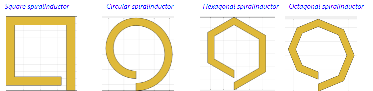
The width and spacing of the strips in the spiral inductor are uniform throughout. You can feed the inductor in such a way that the inner end is routed out from the layer below the inductor by a via hole or the input port and the outer end or output port is extended to the end of the board at the same layer .
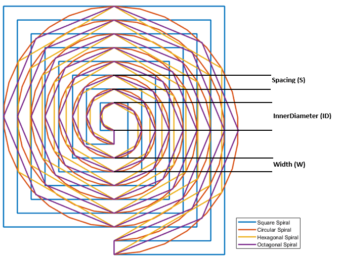
The figure shown below consists of four spiral inductors along with their physical parameters to model spiral inductors
Planar Spiral Inductor in Embedded Microstrip Form with Homogeneous Substrate
Create and analyze a multiturn spiral inductor with different configurations like square, circular, hexagonal, and octagonal by changing the property SpiralShape. Calculate the measure of inductance at 600 MHz.
Square Spiral Inductor
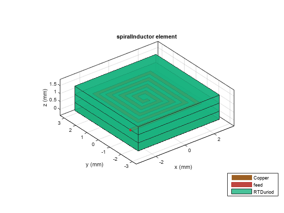
Create and analyze a multiturn square spiral inductor.
Ind = spiralInductor('SpiralShape','square');
figure; show(Ind);
Use the sparameters function to compute the s-parameters and plot it using the rfplot function.
spar = sparameters(Ind,linspace(300e6,800e6,21));
figure;
rfplot(spar);
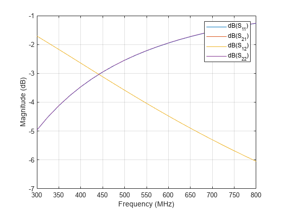
The s-parameters plot shows that after 430 MHz the S11/S22 is monotonically increasing towards 0 dB and S12/S21 is decreasing accordingly. This plot tells that the energy is stored in inductor and not radiated. The behavior of S11 and S21 satisfies the law of conservation of energy.
Use the inductance function to plot the measure of inductance of the square spiral inductor at 600 MHz and view the mesh.
Ls = inductance(Ind,600e6)
Ls =
5.0708e-08
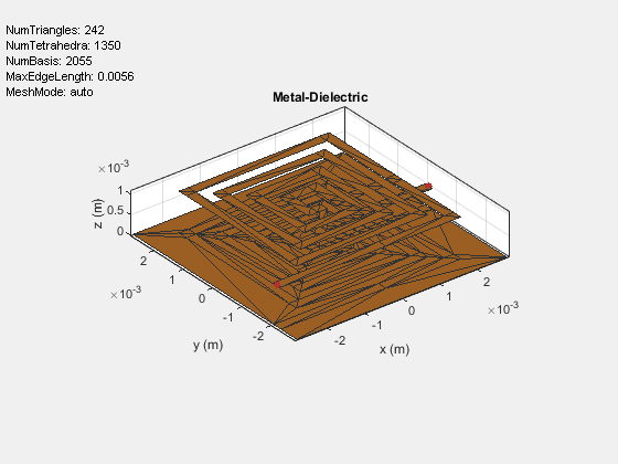
figure; mesh(Ind,'View','Metal');
Circular Spiral Inductor
Create and analyze multiturn circular spiral inductor.
Ind = spiralInductor('SpiralShape','circle');
figure; show(Ind);

Use the inductance function to calculate the measure of inductance of the circular spiral inductor at 600 MHz.
Lc = inductance(Ind,600e6)
Lc =
4.4512e-08
Octagonal Spiral Inductor
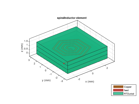
Create and analyze a multiturn octagonal spiral inductor.
Ind = spiralInductor('SpiralShape','Octagon');
figure; show(Ind);

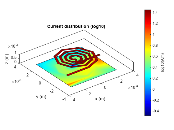
Use the current function to plot the current distribution on the surface of the octagonal spiral Inductor.
figure;
current(Ind,600e6,'scale','log10');
Use the inductance function to plot the measure of inductance of the octagonal spiral inductor at 600 MHz.
Lo = inductance(Ind,600e6)
Lo =
4.1891e-08
Hexagonal spiral Inductor
Create and analyze multiturn hexagonal spiral inductor.
Ind = spiralInductor('SpiralShape','Hexagon');
figure; show(Ind);
Use the inductance function to calculate the measure of inductance of the hexagonal spiral inductor at 600 MHz.
Lh = inductance(Ind,600e6)
Lh =
4.0503e-08
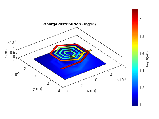
Use the charge function to plot the charge distribution on the surface of the octagonal spiral Inductor.
figure;
charge(Ind,600e6,'scale','log10');
The Magnitude of inductance for the different configurations of the four turn spiral inductors are shown in the table below. It is observed that the inductance of the square spiral inductor is more when compared to the rest of the spiral shapes.
Shape = {'Square';'Circle';'Octagon';'Hexagon'};
Inductance_nH = [Ls;Lc;Lo;Lh]./1e-9;
T = table(Shape,Inductance_nH)T=4×2 table
Shape Inductance_nH
___________ _____________
{'Square' } 50.708
{'Circle' } 44.512
{'Octagon'} 41.891
{'Hexagon'} 40.503
The magnitude of the inductance increases as the length of the inductor and area increases. It is evident from the figures shown for the four configurations of spiral inductors, that the inductance of spiral inductors increases with the increase in trace length and area of the inductors such that: Square> Circular>Octagonal>Hexagonal. The circular and square structures are most popular of the spiral inductors because of less complex analytical design and ease of fabrication. However, other polygonal spirals have also been used in circuit design. Some designers prefer polygons with more than four sides to improve performance of quality factor of the spiral inductors.
Reference
Sunderarajan S. Mohan, Maria del Mar Hershenson, Stephen P. Boyd, and Thomas H. Lee, “Simple Accurate Expressions for Planar SpiralInductances,” IEEE Journal Of Solid-State Circuits, Vol. 34, No. 10, pp. 1419-1424, October 1999.