Brake Motion Using Clutches
A special case of transferring motion occurs when you want to brake the spinning of a driveline component, slowing it down until it stops. The common way to brake the motion is to couple the spinning component to a rotational ground. You can represent a rotational ground with a Mechanical Rotational Reference block from the Simscape™ Foundation library. Because a rotational ground cannot move, a driveline axis locked to a rotational ground also cannot move. You can implement the gradual engagement or disengagement of a driveline component with a rotational ground using a clutch, just as you use a clutch to couple or uncouple two spinning shafts gradually.
Braking with a Two-Clutch System
Open the model. At the MATLAB® command prompt, enter
openExample('sdl/ClutchesForAcceleratingAndBrakingExample')The model features two clutches, one of which acts as a brake. The model also includes frictional damping for greater realism. The simulation time is set to
inf(infinity). For simplicity, the model uses the Disk Friction Clutch block.Clutch Model with Brake Clutch
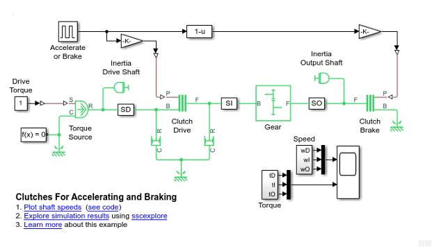
This model uses the basic structure of inertia—clutch—gear—inertia. The first body, Inertia Drive Shaft block, is driven by an external torque, and the initial velocities are 0. There is, however, another clutch for the second body, Inertia Output Shaft block, that can couple Inertia Output Shaft to the Mechanical Rotational Reference block and bring it to a stop.
The switching assembly is based on the clutch switch. You can change this switch to apply a constant clutch pressure signal to either the Clutch Drive block or the Clutch Brake block. The Fcn 1–u block ensures that the full clutch pressure is applied to either one or the other, but not both at once. The Damper blocks apply viscous (velocity-dependent) friction to the spinning of the Inertia Drive Shaft and the Inertia Output Shaft.
The Accelerate or Brake block is programmed to provide a signal of
1for the first 40 seconds of the simulation. It provides a signal of0for the following 60 seconds of the simulation.Start the model.
During the first 40 seconds, when the Accelerate or Brake block is set to 1, the clutch pressure is applied to the Gear clutch. The Gear clutch engages and locks the driver and driven shafts and causes them to rotate at the same velocity.
The Inertia Output Shaft is on the other side of the Simple Gear. The angular velocity of the Inertia Drive Shaft is twice that of the Inertia Output Shaft because the gear ratio of the Simple Gear block is 2, follower to base. In this switch mode, no clutch pressure is applied to Brake Clutch, which remains unengaged.
After an initial transient, the system settles into a steady state of motion where the external torque balances the friction losses.
At t = 40 seconds, the Accelerate or Brake block switches to
0to disengage the gear clutch and engage the brake clutch. The system undergoes another transient while the Gear clutch disengages and Brake clutch engages.The angular velocity of Inertia Drive Shaft and the driver shaft settles down to a new steady state of 10 radians/second, twice its old speed.
Because the Gear clutch is now disengaged, the driven shaft and the Inertia Output Shaft are no longer subject to a driving torque through Gear clutch. But the Brake clutch is engaged and couples the Inertia Output Shaft to the immobile Mechanical Rotational Reference. Once engaged, the kinetic friction of the Clutch Brake brings the driven shaft and the Inertia Output Shaft to a stop.
To see the transient behavior at simulation start and when you switch the clutches:
Start the simulation and let it run for a short time. Then switch Clutch Switch to the other mode.
After a short time, stop the simulation. Use the Autoscale feature of the Scopes to capture the entire simulation sequence. The transients from the starting behavior and the switching transition are visible.
For example, in these plots, the model was started with Clutch Switch set to 1 (Gear clutch locked, Brake clutch disengaged, no braking). The velocities quickly climbed to their steady-state values. Then Clutch Switch was changed at 40 seconds of simulation time. Gear clutch disengaged and Brake clutch engaged, braking Inertia2. The angular velocity of the driver shaft rose from 5 to 10 radians/second. The angular velocity of the driven shaft dropped from 5 to 0. The angular velocity of Inertia2 dropped from 2.5 to 0.
![]()