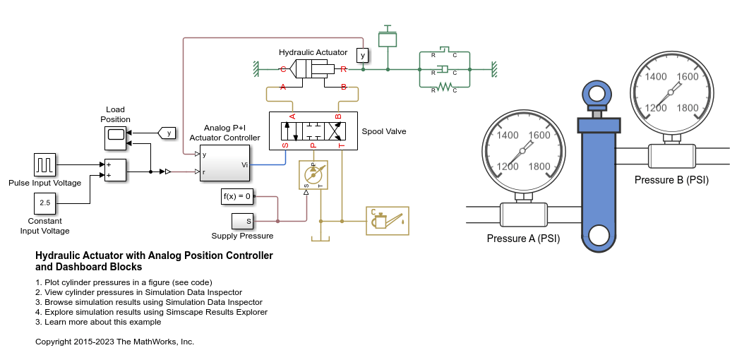
Hydraulic Actuator with Analog Position Controller and Dashboard Blocks
Warning: This example uses the hydraulic domain, which will be removed in a future release. Find an equivalent example model that uses the isothermal liquid domain here: Hydraulic Actuator with Analog Position Controller and Dashboard Blocks. To convert models to the isothermal liquid domain, use the hydraulicToIsothermalLiquid tool.
This example shows how to use the Foundation library to model systems that span electrical, mechanical and hydraulic domains.
In the model, a hydraulic system controls mechanical load position in response to a voltage reference demand. If the reference demand is zero, then the hydraulic actuator (and load) displacement is zero, and if the reference is +5 volts, then the displacement is 100 mm.
The proportional plus integral controller is implemented using op-amps, the final stage of which is set up as a current source. This then drives a torque motor with resistance and inductance terms modeled. The torque motor directly actuates the spool valve, which in turn controls the main hydraulic circuit supplying the hydraulic ram. Finally, the ram drives a generic mechanical load.
A model with this level of fidelity is ideal to support the servo-valve controller design and testing. It includes the electromechanical high frequency modes that affect stability margins, as well as nonlinear flow rate effects when large demands are made from the hydraulics.
This example includes animations of the actuator and pressure gauges created using a Vertical Gauge block and two Circular Gauge blocks from the Simulink / Dashboard / Customizable Blocks library.
Model

Actuator Control Circuit Subsystem

Spool Valve Subsystem

Motor Control Circuit Subsystem

Simulation Results from Scopes

Simulation Results from Simscape Logging
The figure below shows the cylinder pressures and load position plotted in a MATLAB figure. You can also view this data in the Simulation Data Inspector by clicking the View cylinder pressures hyperlink in the model canvas or by clicking the Data Inspector button on the model Simulation tab.
