Main Content

Assignment

Assign values to specified elements of signal

  • Assignment block

Libraries:
Simulink / Math Operations
HDL Coder / Math Operations

Description

The Assignment block assigns values to specified elements of the signal. You specify the indices of the elements to be assigned values either by entering the indices in the block dialog box or by connecting an external indices source or sources to the block. The signal at the block data port, U, specifies values to be assigned to Y. The block replaces the specified elements of Y with elements from the data signal.

Based on the value you enter for the Number of output dimensions parameter, a table of index options is displayed. Each row of the table corresponds to one of the output dimensions in Number of output dimensions. For each dimension, you can define the elements of the signal to work with. Specify a vector signal as a 1-D signal and a matrix signal as a 2-D signal. To enable an external index port, in the corresponding row of the table, set Index Option to Index vector (port) or Starting index (port).

For example, assume a 5-D signal with a one-based index mode. The table in the Assignment block dialog changes to include one row for each dimension. If you define each dimension with the following entries:

RowIndex OptionIndex
1Assign all 
2Index vector (dialog)[1 3 5]
3Starting index (dialog)4
4Starting index (port) 
5Index vector (port) 

The assigned values are Y(1:end,[1 3 5],4:3+size(U,3),Idx4:Idx4+size(U,4)-1,Idx5)=U, where Idx4 and Idx5 are the input ports for dimensions 4 and 5.

When using the Assignment block in normal mode, Simulink® initializes block outputs to zero even if the model does not explicitly initialize them. In accelerator mode, Simulink converts the model into an S-Function. This involves code generation. The code generated may not do implicit initialization of block outputs. In such cases, you must explicitly initialize the model outputs.

You can use the block to assign values to vector, matrix, or multidimensional signals.

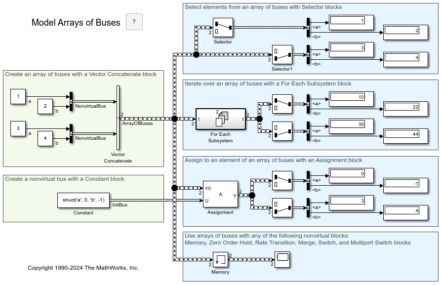
You can use an array of buses as an input signal to an Assignment block.

Assignment Block in Conditional Subsystem

If you place an Assignment block in a conditional subsystem block, a hidden signal buffer (which is equivalent to a Signal Copy block) is inserted in many cases, and merging of signals from Assignment blocks with partial writes can cause an error.

However, if you select the Ensure outport is virtual parameter for the conditional subsystem Outport block, such cases are supported and partial writes to arrays using Assignment blocks are possible. See Ensure Output Port Is Virtual.

Examples

Limitations

  • The Index parameter is not tunable during simulation. If the Index Option for a dimension is set to Index vector (dialog) or Starting index (dialog) and you specify a symbolic value, including a Simulink.Parameter object, for the corresponding Index in the block dialog, then the instantaneous value at the start of simulation will be used throughout the simulation, and the parameter will appear as an inlined value in the generated code. See Tune and Experiment with Block Parameter Values. You can adjust the assignment index dynamically by using index ports.

Ports

Input

expand all

The initialization signal for the output signal. If an element is not assigned another value, then the value of the output element matches this input signal value.

Data Types: single | double | int8 | int16 | int32 | int64 | uint8 | uint16 | uint32 | uint64 | fixed point | Boolean | enumerated | bus

Value assigned to the output element when specified.

Data Types: single | double | int8 | int16 | int32 | int64 | uint8 | uint16 | uint32 | uint64 | fixed point | Boolean | enumerated | bus

External port specifying an index for the assignment of the corresponding output element.

You can specify integer of custom width (for example, a 15-bit integer or 23-bit integer) as an index signal value. When you configure the width of the integer, you must specify the Mode as Fixed point, with Word length less than or equal to 65,535, Slope equal to 1, and Bias equal to 0. For more information on specifying a fixed-point data type, see Specify Data Types Using Data Type Assistant.

Dependencies

To enable an external index port, in the corresponding row of the Index Option table, set Index Option to Index vector (port) or Starting index (port).

Data Types: single | double | int8 | int16 | int32 | uint8 | uint16 | uint32

Output

expand all

The output signal with assigned values for the specified elements.

Data Types: single | double | int8 | int16 | int32 | int64 | uint8 | uint16 | uint32 | uint64 | fixed point | enumerated | bus

Parameters

expand all

Enter the number of dimensions of the output signal.

Programmatic Use

Parameter: NumberOfDimensions
Type: character vector
Values: integer
Default: '1'

Select the indexing mode. If One-based is selected, an index of 1 specifies the first element of the input vector. If Zero-based is selected, an index of 0 specifies the first element of the input vector.

Programmatic Use

Parameter: IndexMode
Type: character vector
Values: 'Zero-based' | 'One-based'
Default: 'One-based'

Define, by dimension, how the elements of the signal are to be indexed. From the list, select:

Menu ItemAction
Assign all

All elements are assigned.

Index vector (dialog)

Enables the Index column. Enter the indices of elements.

Index vector (port)

The index port defines the indices of elements.

Starting index (dialog)

Enables the Index column. Enter the starting index of the range of elements to be assigned values.

Starting index (port)

The index port defines the starting index of the range of elements to be assigned values.

If you choose Index vector (port) or Starting index (port) for any dimension in the table, you can specify one of these values for the Initialize output (Y) parameter:

  • Initialize using input port <Y0>

  • Specify size for each dimension in table

Otherwise, Y0 always initializes output port Y.

The Index and Output Size columns are displayed as relevant.

Programmatic Use

Parameter: IndexOptionArray
Type: cell array of character vectors
Values: {'Assign all'} | {'Index vector (dialog)'} | {'Index vector (port)'} | {'Starting index (dialog)'} | {'Starting index (port)'}
Default: {'Index vector (dialog)'}

For a character vector instead of a cell array of character vectors, use IndexOptions.

If the Index Option is Index vector (dialog), enter the index of each element you are interested in.

If the Index Option is Starting index (dialog), enter the starting index of the range of elements to be selected. The number of elements from the starting point is determined by the size of this dimension at U.

Programmatic Use

Parameter: IndexParamArray
Type: cell array of character vectors
Values: integers
Default: {'1'}

For a character vector instead of a cell array of character vectors, use Indices.

Enter the width of the block output signal.

Dependencies

To enable this column, set Initialize output (Y) to Specify size for each dimension in table.

Programmatic Use

Parameter: OutputSizeArray
Type: cell array of character vectors
Values: integers
Default: {'1'}

For a character vector instead of a cell array of character vectors, use OutputSizes.

Specify how to initialize the output signal.

  • Initialize using input port <Y0> – Signal at the input port Y0 initializes the output.

  • Specify size for each dimension in table – Requires you to specify the width of the block output signal in the Output Size parameter. If the output has unassigned elements, the value of those elements is undefined.

Dependencies

To enable this parameter, set Index Option to Index vector (port) or Starting index (port) for one or more dimensions.

Programmatic Use

Parameter: OutputInitialize
Type: character vector
Values: 'Initialize using input port <Y0>' | 'Specify size for each dimension in table'
Default: 'Initialize using input port <Y0>'

Specify whether to produce a warning or error if you have not assigned all output elements. Options include:

  • Warning — Simulink displays a warning and continues the simulation.

  • Error — Simulink terminates the simulation and displays an error.

  • None — Simulink takes no action.

Dependencies

To enable this parameter, set Index Option to Index vector (port) or Starting index (port) for one or more dimensions. Then, set Initialize output (Y) to Specify size for each dimension in table.

Programmatic Use

Parameter: DiagnosticForDimensions
Type: character vector
Values: 'Error' | 'Warning' | 'None'
Default: 'Warning'

Specify the time interval between samples. To inherit the sample time, set this parameter to -1. For more information, see Specify Sample Time.

Dependencies

This parameter is visible only if you set it to a value other than -1. To learn more, see Blocks for Which Sample Time Is Not Recommended.

Programmatic Use

To set the block parameter value programmatically, use the set_param function.

Parameter: SampleTime
Values: "-1" (default) | scalar or vector in quotes

Select this check box to have Simulink check during simulation in accelerator or rapid accelerator mode whether any index values are outside the range of valid indices for the relevant dimension of the input signal. If an index is out of range, Simulink stops the simulation and displays an error message.

Note

If you do not select this check box, out-of-range index values could lead to undefined behavior during accelerator or rapid accelerator mode simulation.

Simulink performs this check during normal mode simulation regardless of whether you select this check box.

Programmatic Use

Parameter: RuntimeRangeChecks
Type: character vector
Values: 'Off' | 'On'
Default: 'Off'

Block Characteristics

Data Types

Boolean | double | enumerated | fixed point | integer | single

Direct Feedthrough

yes

Multidimensional Signals

yes

Variable-Size Signals

yes

Zero-Crossing Detection

no

Extended Capabilities

C/C++ Code Generation
Generate C and C++ code using Simulink® Coder™.

PLC Code Generation
Generate Structured Text code using Simulink® PLC Coder™.

Fixed-Point Conversion
Design and simulate fixed-point systems using Fixed-Point Designer™.

Version History

Introduced before R2006a

expand all