MultiStateImage
R2026bDisplay images based on signal values on block with customizable appearance
Since R2026b
Custom MultiStateImage block
To add a block to a model, double-click the canvas and start typing the block name. Then, select the block from the list.
Libraries:
Simulink /
Dashboard /
Customizable Blocks
Description
The MultiStateImage block displays images based on the connected signal value. There is a MultiStateImage block in the Dashboard library and in the Customizable Block library. This page pertains to the block in the Customizable Blocks library. When you use the MultiStateImage block in the Customizable Blocks library, you can modify the appearance of the block to resemble a real indicator in your system. Use the MultiStateImage block with other dashboard blocks to build an interactive dashboard of controls and indicators for your model.
To configure the MultiStateImage block, specify one or more states. States pair images you provide with either values or with ranges of values you specify. When the value of the connected signal matches a state value or falls within a state value range, the MultiStateImage block displays the image for that state. When the value of the connected signal does not match any state values or fall within any state value ranges, the MultiStateImage block displays a default image you specify.
Customize MultiStateImage Blocks
When you add a MultiStateImage block to your model, the block is preconfigured with a default design. You can use the block with the default design or customize the appearance of the block.
To customize the appearance of the block, use design mode. After selecting the block, you can enter design mode in one of three ways:
In the Simulink® Toolstrip, on the block-specific tab, click Edit.
In the Property Inspector, on the Design tab, click Edit.
Pause on the ellipsis that appears over the block and click the Edit Custom Block button
 .
.
In design mode, you can use the toolbar above the block to customize the states. To access additional customization options or to enter exact values for design settings, use the Design tab in the Property Inspector.
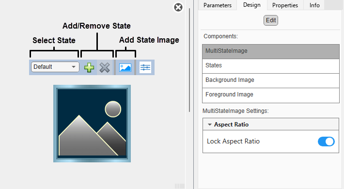
When you customize a MultiStateImage block, you configure the block
appearance for each state. To select a state to customize, use the drop-down list in
the toolbar. Alternatively, in the Property Inspector, on the
Design tab, select the States
component, and then select from the Select State list. To add a
state, in the toolbar, click the Add State button  . To delete a state, click the Remove State button
 .
.
Design Mode Actions that Customize the Selected State
| Action | Available in Toolbar | Available in Design Tab |
|---|---|---|
Specify the state value as a number or a range. | No | Yes |
| Add or remove states. | Yes | Yes |
Upload or replace the image for the state. Supported image file formats include PNG, JPEG, BMP, TIFF, SVG, and GIF. | Yes | Yes |
| Change the size of the image. | No | Yes |
| Change the position of the image. | No | Yes |
| Lock the aspect ratio of the image. | No | Yes |
In addition to customizing the block design using the toolbar and Design tab, you can resize and reposition the image interactively in the canvas. To resize the image for a specific state, select the state in the toolbar, and then resize or reposition the image.
Design Mode Actions that Apply to All States
| Action | Available in Toolbar | Available in Design Tab |
|---|---|---|
Upload a background image. | No | Yes |
Set a solid background color. | No | Yes |
Upload a foreground image. | No | Yes |
To exit design mode, click the X in the upper right of the canvas.
Connect Dashboard Blocks
This block is a display block — a block that connects to a signal and visualizes its value.
Dashboard blocks do not use ports to connect to model elements. Instead, use connect mode. To
enter connect mode on an unconnected block, pause on the block you want to connect and click
the Connect button  . To enter connect mode on a connected block, select the
block, pause on the ellipsis that appears (…), and in the action menu that expands, click
the Connect button.
. To enter connect mode on a connected block, select the
block, pause on the ellipsis that appears (…), and in the action menu that expands, click
the Connect button.
In connection mode, select the signal line to which you want to connect. From the list
that appears, select the signal to which you want to connect. Then, pause on the dashboard
block and click the Done Connecting button . To see the dashboard block display the value of the
connected signal, run the simulation.
For more information about connecting dashboard blocks, see Connect Dashboard Blocks to Simulink Model.
You can also connect dashboard blocks to a Stateflow® chart. For more information, see Connect Dashboard Blocks to Stateflow (Stateflow).
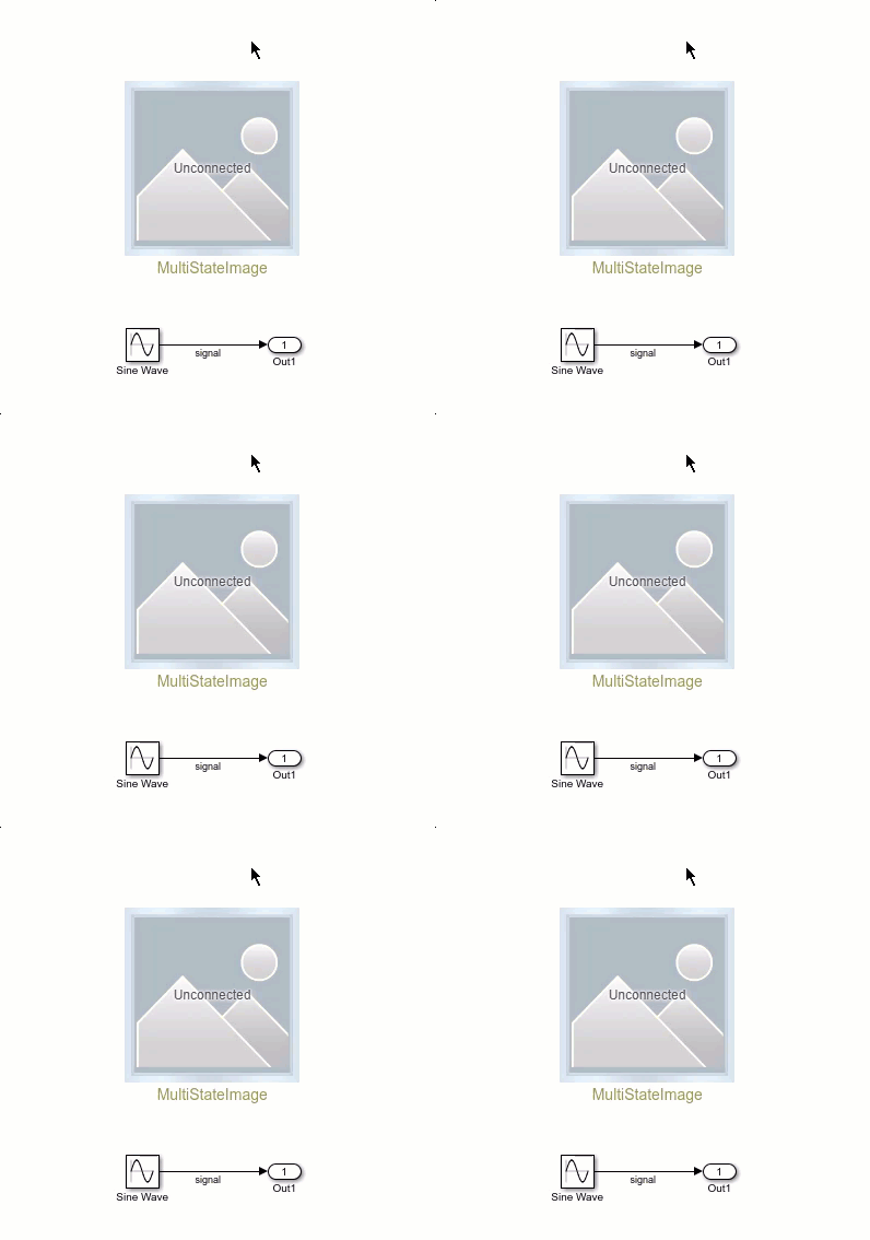
This animation shows how to connect the MultiStateImage block to your model.
Examples
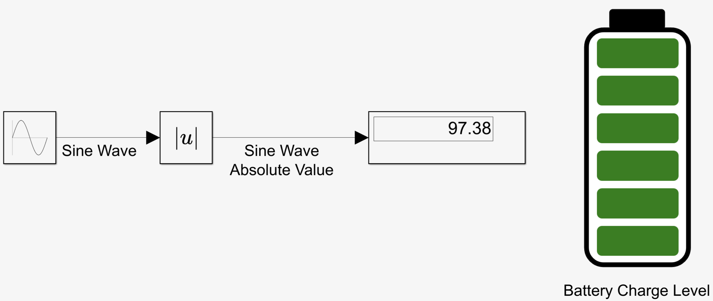
Design Custom Image Displays Based on Signal Value Ranges
Design display of images using the MultiStateImage block.
Limitations
Except for the Dashboard Scope block and the Display block, dashboard blocks can connect only to real scalar signals.
You cannot use the Connection table in the Block Parameters dialog box to connect a dashboard block to a block that is commented out. When you connect a dashboard block to a commented block using connect mode, the dashboard block does not display the connected value until you uncomment the block.
Dashboard blocks cannot connect to model elements inside referenced models.
When you simulate a model hierarchy, dashboard blocks inside referenced models do not update.
Dashboard blocks do not support rapid accelerator simulation.
During simulation, you cannot connect a dashboard block to Stateflow chart data or state activity.
You cannot programmatically connect a dashboard block to Stateflow chart data or state activity.
Some signals do not have data available during simulation due to block reduction or optimization for accelerator mode simulations. To view such a signal using a dashboard block, mark the signal for logging.
Parameters
Block Characteristics
Data Types |
|
Direct Feedthrough |
|
Multidimensional Signals |
|
Variable-Size Signals |
|
Zero-Crossing Detection |
|
Extended Capabilities
Version History
Introduced in R2026b

