Create OLED Display Block to Display Acceleration and Tap Count Using Arduino External Interrupt Block and IO Device Builder App
This example shows how to use the IO Device Builder app to create OLED Display block to display acceleration and tap count using Arduino External Interrupt block.
OLED is a flat light-emitting technology made by placing a series of organic thin films between two conductors. When an electrical current is applied, a bright light is emitted. In this example, the values are displayed using the I2C protocol requiring two wires (SCL and SDA).
Note:
By default, communication libraries such as SPI, I2C, and Servo are included. For information on adding other libraries, see Working with Arduino Libraries in IO Device Builder.
The IO Device Builder app supports only Monitor & Tune (External mode) and Build, Deploy & Start options. Connected IO is not supported.
Prerequisites
Download and extract the following zip files from GitHub®.
Adafruit_SH1106 drivers
Dependent file Adafruit_BusIO
Dependent file Adafruit_GFX_Library
Circuit Connections
To run this example, make these circuit connections.
Connect Arduino® VCC to OLED Module VCC.
Connect Arduino GND to OLED Module GND.
Connect SCL to SCL and SDA to SDA pin from the sensor to Arduino.
Create ADXL343 Sensor Block and OLED Display Block
Create ADXL343 Sensor Block using the steps listed in Create ADXL343 Sensor Block to Read Acceleration Using IO Device Builder App.
After creating the ADXL343 Sensor block, modify the generated .cpp and h files as shown below.
Generated h file.
#ifndef EXAMPLE_H
#define EXAMPLE_H
#if !( defined(MATLAB_MEX_FILE) || defined(RSIM_PARAMETER_LOADING) ||  defined(RSIM_WITH_SL_SOLVER))
#ifdef __cplusplus
#include "rtwtypes.h"
extern "C" {
    #endif
    void stepFunctionadxlSensor(float * x,int size_vector_1,float * y,int size_vector_2,float * z,int size_vector_3);
    void setupFunctionadxlSensor(int8_T * accelRange,int size_vector__1);
    void clearInterrupt(); // Header decleration for clearing the latch interrupt
    #ifdef __cplusplus
}
#endif
#else
#define loop(void) (0)
#define setup(void) (0)
#endif
#endif
Generated .cpp file.
#include "C:\user\adxlSensor\adxlSensor.h"  // App generated header. Do not modify
#include "Wire.h"
#include "Adafruit_Sensor.h"
#include "Adafruit_ADXL343.h"
#include "Arduino.h"
#define ADXL343_SCK 52
#define ADXL343_MISO 50
#define ADXL343_MOSI 51
#define ADXL343_CS 10
Adafruit_ADXL343 accel = Adafruit_ADXL343(ADXL343_CS, &SPI, 12345);
#define INPUT_PIN_INT1   (5)
int_config g_int_config_enabled = { 0 };
int_config g_int_config_map = { 0 };

// Clearing the latch interrupt
void clearInterrupt(){
    accel.checkInterrupts();
}

void setupFunctionadxlSensor(int8_T * accelRange,int size_1){
    while (!Serial);
    if(!accel.begin())
    {
        while(1); // Checking the connections for ADXL343
    }
    accel.setRange(*accelRange);

    g_int_config_enabled.bits.single_tap = true;
  accel.enableInterrupts(g_int_config_enabled);
    g_int_config_map.bits.single_tap = ADXL343_INT1;
  accel.mapInterrupts(g_int_config_map);
}

void stepFunctionadxlSensor(float * x,int size_1,float * y,int size_2,float * z){

    sensors_event_t event;
    accel.getEvent(&event);
    delay(10);

    //Acceleration is measured in m/s^2
    *x=event.acceleration.x;
    *y=event.acceleration.y;
    *z=event.acceleration.z;

}
Perform these steps to create OLED Display block.
Launch the IO Device Builder app.

Select Working Directory and Add Third-Party Source Files
Once the Source files location page loads, select the working directory and add third-party source files.

On the Source files location page:
Click Select and select the working directory. In the working directory, the generated System object™, along with the corresponding cpp and h files, and the model are located.
Click Add folder and add Adafruit_SH1106-master, Adafruit_BusIO-master, and Adafruit-GFX-Library folders you downloaded. Only the files present directly within the selected folder are included, and any files present within subfolders are excluded.
Click Next to continue.
Select Source Files

On the Source files page, select the required source files and then click Next to continue.
Specify Block Parameters
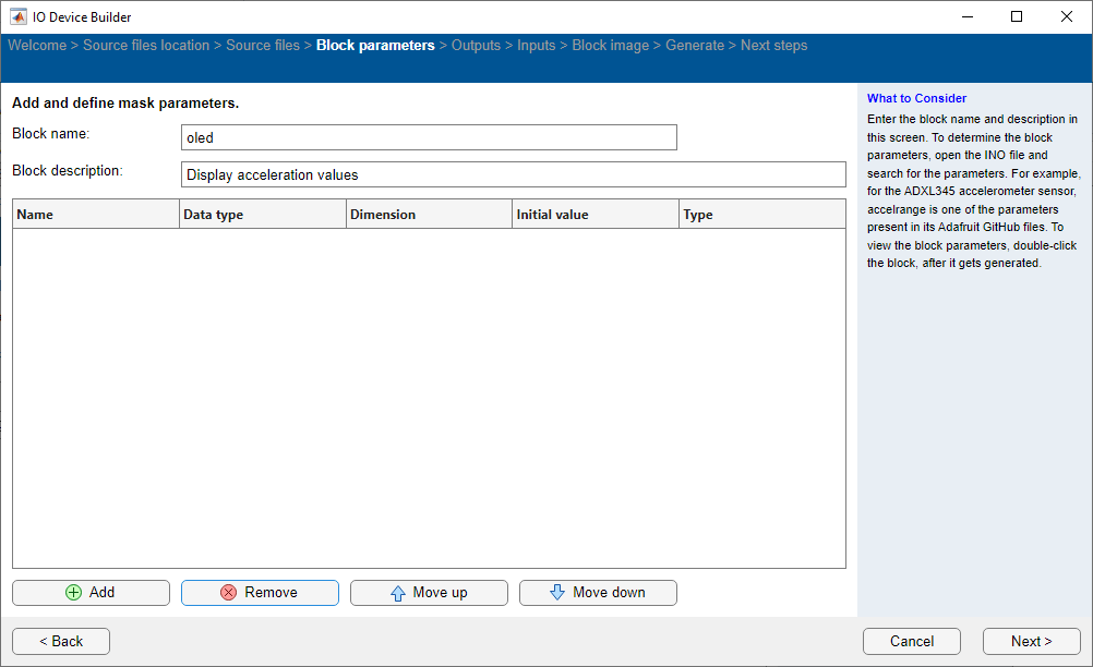
On the Block parameters page:
Specify the block name and add block description.
Remove parameters for the block, if any already added.
Click Next to continue.
Select Outputs for the Block

On the Outputs page:
Remove Output ports for the block, if any already added.
Click Next to continue.
Select Inputs for the Block
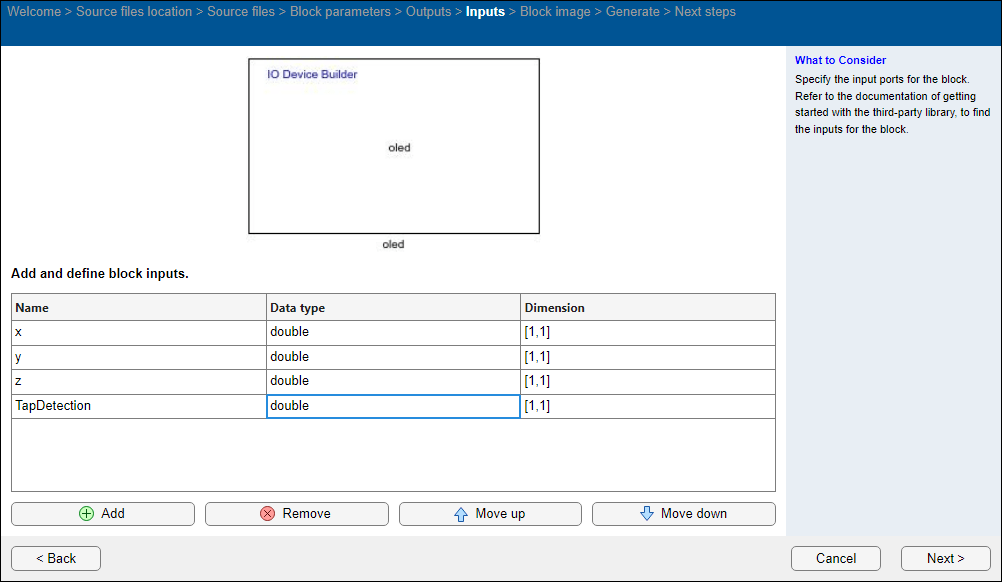
On the Inputs page:
Add inputs
x,y,z, andTapDetectionfor the block, with Data type asdoubleand Dimension as[1,1].Click Next to continue.
Preview Block
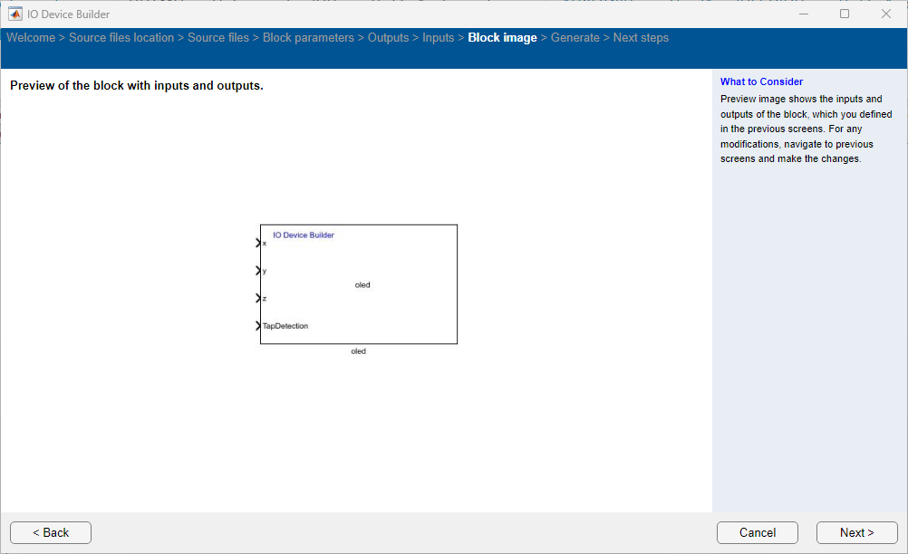
On the Block image page, view the preview of the block with the inputs and outputs you added. Click Next to continue.
Generate System Object Files

The app displays the location of the System object file on the Generate page. Choose the Select to generate a C++ driver option, if you want to generate a C++ file.
Click Generate to generate the System object files.
On the Next Steps page, the files generated are shown and the next steps to be performed are displayed. The generate files are created in a directory. This directory also includes a Dependencies folder that contains selected third-party source files. Simply copy these files and the folder to your desired location and integrate them into your Simulink project.
Click Finish on this page to complete the process. The generated .cpp file opens automatically.
Perform these steps.
1. Modify the generated .cpp file as shown below.
#include "C:\user\oledDisplay\oledDisplay.h"  // App generated header. Do not modify.
#include "Arduino.h"
#include "Wire.h"
#include "Adafruit_GFX.h"
#include "Adafruit_SH1106.h"
#define OLED_RESET -1
Adafruit_SH1106 display(OLED_RESET);
void setupFunctionoledDisplay(){
    display.begin(SH1106_SWITCHCAPVCC, 0x3C);
    display.clearDisplay();
}

void stepFunctionoledDisplay(double x,int size_a,double y,int size_b,double z,int size_c,double TapDetection,int size_d){
    display.clearDisplay();
    display.setTextSize(1);
    display.setTextColor(WHITE);
    display.setCursor(20,2);
    display.print("ADXL Data: ");  // Acceleration value in m/s
    display.setCursor(1,20);
    display.print("X: ");
    display.print(x);
    display.setCursor(1,30);
    display.print("Y: ");
    display.print(y);
    display.setCursor(1,40);
    display.print("Z: ");
    display.print(z);
    display.setCursor(1,50);
    display.print("Tap Detection: ");  // Single tap detection
    display.print(TapDetection);
    display.display();

}
Note: Ensure that you delete or comment out the serial command because Simulink communicates with Arduino over external mode using the Serial Communication Protocol.
2. Assign the output to the selected output port.
3. Add the #include "Arduino.h" header and other required headers for the driver, as mentioned in ino example with the absolute address.
4. In the already opened Simulink model, add a Display block to the output ports.
5. Add Arduino External Interrupt block along with Function Call Subsystem block for the Interrupt workflow. An image for Function Call Subsystem is shown here.

Set the Unit Delay block (1/z) parameters are set as shown in the following image.

The Constant and Add block must have the default values.
In the System Outputs block, enter
clearInterrupt();for System Outputs Function Execution Code parameter.Set the Rate Transition parameters as shown in the following image.

Set the Arduino External Interrupt block Pin number to
5and set the Mode toRising.
6. In the Simulink model, navigate to Modeling > Model Settings > Code Generation > Custom Code > Include Directories and add the ADXL directory path.
7. Navigate to Modeling > Model Settings and in the Configuration Parameters dialog box, click Hardware Implementation and then select an Arduino board and perform Monitor and Tune action.
A sample Simulink model is shown here.
