Author and Import Requirements
R2026bYou can author requirements directly in the Requirements Editor (Requirements Toolbox), or import them from external formats such as Microsoft®
Excel®, Word, or ReqIF. This project uses a Microsoft
Excel spreadsheet (BMSSwRequirements.xlsx) as its starting
point. Linking requirements to architecture elements, model blocks, and test cases
creates a digital thread that enables you to trace coverage from specification through
implementation to verification.
In this section, you:
Author requirements in an Microsoft Excel spreadsheet.
Import requirements into the Requirements Editor.
Map requirement types.
Link requirements to design elements.
Note
For an interactive version of the requirements import and linking workflow, open
Doc/BMSVerificationAndValidation.m in the project.
Author Requirements in Excel
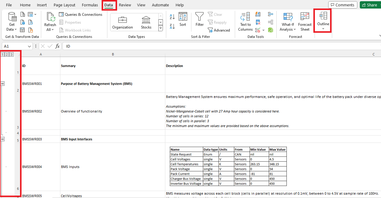
Author requirements for the BMS in BMSSwRequirements.xlsx using
a structured spreadsheet template. The template uses columns for requirement ID,
summary, and description, with spreadsheet outline levels to represent the
requirement hierarchy.
To set up the hierarchy in Microsoft Excel:
Open
BMSSwRequirements.xlsxin theRequirements/folder.Select the rows you want to group as children.
On the Data tab, in the Outline section, click Group.
Repeat for each level of the hierarchy.
The spreadsheet outline levels become parent-child relationships when you import the spreadsheet into the Requirements Editor (Requirements Toolbox).
Import Requirements
Import the Microsoft Excel spreadsheet into the Requirements Editor to create a requirements set that you can link to models, tests, and architecture elements.
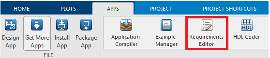
To open the Requirements Editor, on the MATLAB® toolstrip, on the Apps tab, click Requirements Editor.
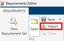
To import from the spreadsheet, click Import > From File.
In the Import dialog box:
In the Source document section, set the Document Location field to
BMSSwRequirements.xlsxand the Document Type field toMicrosoft Excel Spreadsheet.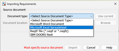
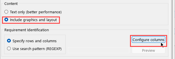
In the Content section, select Include graphics and layout.
To configure column mapping, click Configure columns:
Map the Microsoft Excel columns as follows:
ID → Custom ID
Summary → Summary
Description → Description
From the Post-Import Callback dropdown, select
excelHierarchyImport.m. This script is in theScripts/folder. It preserves the spreadsheet outline hierarchy as parent-child relationships in the imported requirements set.Click Import.
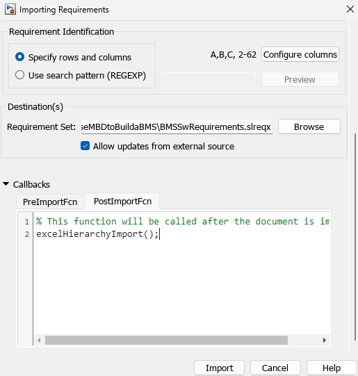
The import saves the requirements as BMSSwRequirements.slreqx
in the Requirements/ folder. To open the imported requirements
set, run this command:
open("BMSSwRequirements.slreqx")Map Requirement Types
After importing, assign a requirement type to each requirement. Types distinguish among context that provides background (Informational), testable specifications (Functional), and organizational headings (Container).
|
Requirement Container |
Type |
Rationale |
|---|---|---|
|
Purpose of BMS |
Informational |
High-level system context, not directly testable |
|
BMS Input Interfaces |
Functional |
Specifies expected inputs — testable against model ports |
|
BMS Output Interfaces |
Functional |
Specifies expected outputs — testable against model ports |
|
BMS Architecture and Module Specification |
Functional |
Component-level behavioral specifications — testable against implementation |
To set the requirement type, select a requirement in the Requirements Editor and set the Type property in the Properties pane.
Link functional requirements to architecture components to establish traceability from specification to design. Only functional requirements map to testable design elements. Informational and container types provide context but do not require implementation coverage.

Link Requirements to Design Elements
To establish traceability across the design lifecycle, link requirements to architecture elements, model blocks, and test cases. These links enable you to:
See which components implement each requirement.
Identify requirements that lack implementation or test coverage.
Navigate from a requirement to the design that implements it or the test that verifies it.
To create a link:
Select a requirement in the Requirements Editor.
Right-click and select Select for linking with.
Navigate to the target element. A target element can be an architecture component in System Composer, a block in Simulink®, or a test case in Simulink Test™.
Right-click the target element and select Link to Selected Requirement.
In this BMS project, requirements link to:
Architecture components — Link to components of the
BMSAlgorithmArchitecturesoftware architecture model to establish requirements to architecture traceability.Simulink model blocks — Link to blocks in the
StateMachineandCellMonitoringAndBalancingmodels to establish requirements to implementation traceability.Test cases — Link to test cases in the
StateMachineTestfile to establish requirements to verification traceability.
Alongside each model, traceability files (.slmx) store these
links. For example, StateMachine~mdl.slmx stores the links
between StateMachine.slx and its associated requirements.
See Also
Requirements Editor (Requirements Toolbox) | Requirements Manager (Requirements Toolbox) | slreq.import (Requirements Toolbox)
Topics
- Import Requirements from a Microsoft Excel Document (Requirements Toolbox)
- Create and Store Links (Requirements Toolbox)
- Visualize Links with Traceability Diagrams (Requirements Toolbox)
- Verify and Validate System

