Reduce Variant Models Using Variant Reducer
Note
This functionality requires Variant Manager for Simulink®.
Variant Reducer
In Simulink, variant elements allow you to represent all possible design variations of a system in a single model. A model might contain several variant blocks or variant parameters, each with many variant choices. A variant configuration is used to represent a combination of such variant choices across the model hierarchy. For example, a vehicle model can have multiple variation points such as car body type, engine type, or transmission type. Using Variant Manager, you can define multiple variant configurations for the model such as a diesel engine sedan with manual transmission or an electric engine SUV with automatic transmission. For more information on variant configurations, see Variant Configurations. For an overview of Variant Manager, see Variant Manager for Simulink.
You can use the Variant Reducer tool in Variant Manager to automatically generate a simplified, standalone model that contains only a subset of variant configurations from the input model. The generated model is called a reduced model. The reduced model retains the variant configurations that you choose from the parent variant model.

High-Level Steps in Reduction Process
Variant Reducer performs these high-level operations during the reduction process:
Removes inactive model components based on the variant configurations that you choose to retain in the reduced model.
Removes or modifies model components such as blocks, variant parameter objects, masks, model references, subsystem references, libraries, dependent files such as MAT or SLDD files, and variables in the input model. For information on model components that are modified or not reduced, see Considerations for Variant Reduction.
Packages the reduced artifacts into a user-specified output folder.
Generates a detailed summary of the reduction process that helps you to analyze these changes.
Modes and Options for Variant Reduction
Variant Reducer provides different modes and options that you can set before reducing the model.
| Mode | Purpose |
|---|---|
Reduction mode | Provides multiple ways to specify the configurations to be retained in the reduced model. You can choose configurations based on:
|
Compile mode | Compile the input model in simulation or code generation mode as part of the reduction process. |
| Option | Purpose |
|---|---|
Files to exclude | Exclude Simulink model files ( |
Output folder | Folder to place the reduced model and artifacts |
Model suffix | Suffix to append to the name of reduced model and artifacts |
| Remove Variant Subsystem layer | Remove outer layer of a Variant Subsystem block when only one of the choices of the variant subsystem remains active in the reduced model. |
| Preserve signal attributes | Try to preserve compiled signal attributes between the original and the reduced model by adding signal specification blocks in the reduced model. |
| Open reduced model | Change the current working folder to the output folder specified for reduction and open the reduced model. |
| Generate detailed summary | Generate a detailed summary for the reduced model. This requires a Simulink Report Generator™ license. |
Note
To reduce a model programmatically, see Simulink.VariantManager.reduceModel.
Video Walkthrough
For a visual walkthrough of the example, watch the video.

Steps to Reduce Variant Model
Open Variant Manager for the model that must be reduced. Here, open the
slexVariantReducermodel using the following command.openExample('simulink_variants/ReduceAVariantModelForSelectedVariantConfigurationExample');On the Modeling tab, open the Design section and click Variant Manager. Alternatively, right-click the variant badge on any variant block in the model and select Open in Variant Manager.

This image shows the Variant Manager window for the
slexVariantReducermodel. The model has two predefined variant configurations namedconfig1(V == 1 && W == 2) andconfig2(V == 2 && W == 2).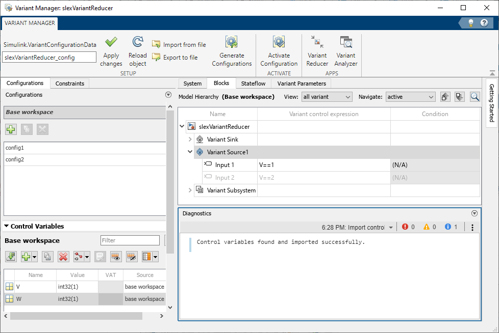
Open Variant Reducer. In the Variant Manager toolstrip, in the Apps section, click Variant Reducer.
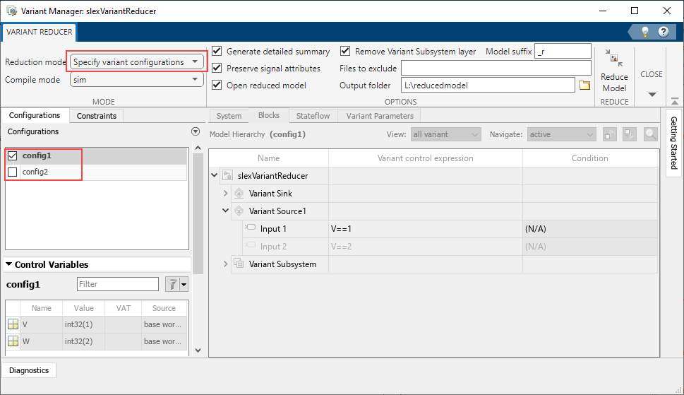
This image shows the Variant Reducer window.

Specify the different settings for reduction in the Mode and Options sections of the Variant Reducer toolstrip. If you do not modify the settings, Variant Reducer uses default values for reduction. The purpose of each setting is detailed in the following steps.
Select a Reduction mode option:
Current variant control values: Reduce the model based on the variant control variable values in the base workspace or data dictionary used by the model.
Specify variant configurations: Reduce the model for the named configurations defined in a variant configuration data object associated with the model.
Note
In this mode, Variant Reducer stores the variant control variable values from the last selected configuration in the base workspace or data dictionary used by the model.
Select the required configurations from the Configurations tab.
Specify variant control values: Reduce the model by specifying values for the variant control variables. If the model does not have any predefined named configurations, Variant Reducer uses this mode by default. You can create multiple variable groups that correspond to different variant configurations to be retained in the reduced model. In each variable group, you must specify the variant control variables and the values to be considered for each variable.
Note
In this mode, the reduced model has a new variant configuration data object that contains the specified variable groups.

To add a new variable group, click
 in the Variable Groups
table.
in the Variable Groups
table.In the Group table, in the Values column, you can either specify a value for the variant control variable or select
Full-rangeorIgnoredfrom the list.Variant control value as a vector — Reduce the model for all combinations of the specified values. For example, if you specify values
V = 1andW = [1,2], then the model is reduced for the configurations{V == 1, W == 1}and{V == 1, W == 2}.Full-range— Reduce the model for all valid values of the specified variant control variable. In the Reference value column, you must enter a reference value for the variable for which the model compiles successfully.Ignored— The variant control variable is not considered while reducing the model.
Note
To use a full-range variant control variable, you must set the Variant activation time in the block parameters dialog of the block that uses that variant control variable to a value other than
update diagram.You can specify at most one full-range variant control variable in a variant block.
Specifying the value of a variant control variable as
full-rangeduring reduction is not supported if the variable is used by variant parameters visible to the model, even if the parameter is not used in the model hierarchy.
For Compile mode, select
simto compile the model for simulation orcodegento compile the model in code generation mode as part of reducing the model. If the model contains variant blocks with the Variant control mode parameter set tosim codegen switching, you can selectcodegento retain the code generation branches of the blocks in the reduced model. For the default valuesim, Variant Reducer compiles and retains the simulation branches in the top-level model.Select Preserve signal attributes to preserve the compiled signal attributes between the original and reduced model. When this option is selected, the Variant Reducer tries to preserve the compiled signal attributes between the original and reduced models by adding signal specification blocks at appropriate block ports in the reduced model. Compiled signal attributes include signal data types, signal dimensions, and compiled sample times.
Select Generate detailed summary to generate the Variant Reducer summary report in the output folder. The Variant Reducer summary contains a summary of Variant Reducer Options, Original and Reduced Model Differences, Dependent Artifacts, Callbacks, and Warnings. For more information, see Explore Variant Reducer Summary.
Note
To generate a detailed summary, you must have a Simulink Report Generator license.
Use the Files to exclude box to specify any files that Variant Reducer must exclude from the reduction process. The value must be a character vector, string array, or a cell array of character vectors or string arrays.
You can exclude:
Simulink model files (
*.slx,*.mdl)Simulink data dictionary files (
*.sldd)MAT files (
*.mat)
You can specify the full path of the folder or the specific files that must be excluded, which can include wildcard characters, for example,
'components\*.slx',{'mylib.slx','myssref.slx'},'*.sldd', or'topData.sldd'.For additional information, see Excluded Files in Model Components That Are Not Reduced.
The Remove Variant Subsystem layer check box is selected by default. This setting removes the outer layer of a Variant Subsystem block when only one choice of the variant subsystem remains active in the reduced model.
Variant Reducer moves the block which is the active choice to the top level and removes the Variant Subsystem block from the reduced model. Removing the additional layer helps to make the reduced model easy to read and navigate.
Specify a value for Model suffix. The model suffix value is appended to the names of the reduced models, data dictionaries, and related artifacts. By default, the suffix is
_r.In the Output folder box, browse for or enter the output folder in which to store the reduced model and related artifacts. The output folder must not be under
matlabroot. By default, the reduced artifacts are generated in a folder namedreducedModelwithin the original model folder.If the output folder contains the
variant_reducer.logfile from a previous model reduction, then Variant Reducer overwrites all the files available in that folder during any subsequent reduction.Select Open reduced model to change the current working folder to the output folder and open the reduced model.
Click Reduce Model.
This image shows the result of reducing the model for the configuration
config1with valuesV = 1andW = 2.
To return to the Manage tab of Variant Manager, click Close Variant Reducer.
Explore Variant Reducer Summary
If you set the Generate detailed summary option for a reduction, Variant Reducer generates a detailed report of the reduction process as an HTML file. The report is saved in the output folder where reduced artifacts are saved.
Note
A Simulink Report Generator license is required to generate a Variant Reducer summary.
Use the Variant Reducer summary to:
Verify the input and output options used for reduction, for example, the input variant configuration and the output folder location.
Analyze the differences between the original model and the reduced model, for example:
Blocks that have been inserted, moved, deleted, or modified
Masks that have been modified
Dependent data files or Simulink cache files that have been modified
Identify any warnings.
Identify components that are not reduced and determine the manual updates that might be required, for example, callback code and Stateflow® variant transitions.
Navigate the interactive views of the original and reduced models.

Considerations for Variant Reduction
Variant Conditions on Simulink Function Blocks After Reduction
If a model that contains a Simulink Function block is reduced for any or a combination of the available variant conditions on the block, then the Simulink Function block in the reduced model becomes unconditional.
Consider a model that contains a Simulink Function block with the value
of the Variant control parameter set to V == 1 || V == 2 ||
V == 3 || V == 4.
If the model is reduced for the variant control values
V = 1,V = 2, andV = 3, then the Simulink Function block in the reduced model is unconditional.If the model is reduced for the variant control values
V = 1,V = 2, andV = 5, then the Simulink Function block in the reduced model remains conditional with the value of the Variant control parameter set toV == 1 || V == 2.
Modifications to Model Components
Additional blocks are added automatically to the reduced model to maintain consistent simulation semantics. Additional blocks include:
Signal Specification blocks for consistent signal attributes such as data type, dimensions, and complexity
Ground and Terminator blocks for unconnected signals
Single input and single output Variant Source block with Variant control mode set to
labelto retain the signal names
Variant parameter objects (instance of the
Simulink.VariantVariableclass) are reduced.Referenced models, referenced subsystems, and library blocks present in the model hierarchy are reduced.
If the model contains resolved library links, the corresponding parent is reduced for the specified configuration and is referenced in the model.
Reduced models are saved with a MAT file that contains saved variant configurations. The file loads during the
PostLoadFcncallback of the reduced model.Variant Subsystem blocks with only one choice are converted to normal Subsystem or Model blocks.
If the Remove Variant Subsystem layer option is selected and only one choice of a Variant Subsystem block remains active after reduction, the block that represents the active choice is moved to the top level and the Variant Subsystem block is removed from the reduced model. The action reconnects the signal lines that were present on the removed block to the active choice.
Single-input, single-output Variant Source and Variant Sink blocks are removed if they are active across all specified configurations.
During model reduction, commented blocks present on the active path are retained. Commented blocks present on an inactive path are removed.
Signal attributes such as data type, complexity, or dimensions that come from the inactive elements in Stateflow charts might not be retained in the reduced model.
Unused variables are removed from Simulink data dictionary files (
*.sldd) and MAT files (*.mat).For a Variant Assembly Subsystem block in expression mode that uses an enumeration to add variant choices, Variant Reducer generates reduced enumeration definitions that retain only the members corresponding to the retained variant configurations. Depending on the definition in the parent model, the reduced enumeration is defined either in a class file, in a reduced data dictionary, or in the
PostLoadFcncallback of the reduced model using the functionSimulink.defineIntEnumTypefor in-memory enumerations in the MATLAB® workspace.
Model Components That Are Not Reduced
These model components are not reduced automatically and might require manual intervention. To identify such artifacts, use the Variant Reducer summary report.
Callback code:
Callbacks such as
InitFcn,PreLoad,PostLoad, mask initialization code, and mask parameter callback code must be modified manually.Callback code in the inactive variant components is removed. This action can cause unexpected behavior in the reduced model.
Constraints defined on variant configurations are not deleted. Variant control variables used to define the constraints are not deleted from Simulink data dictionary files (
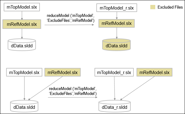
*.sldd), MAT files (*.mat), and the variant configuration data object for the model.Excluded files:
Variant reducer does not modify or copy excluded files to the output folder after reduction. The reduced model, if needed, will refer to these files from their original location. Files inside the MATLAB root folder are excluded by default.
When you exclude a file that is in the original model’s hierarchy, that is, when the excluded file is used by the model, then Variant Reducer automatically identifies and excludes from the reduction the dependent models and data dictionaries used by the excluded file. The list of excluded dependent files is available in the
variant_reducer.logfile and the generated summary.When you exclude a file that is not in the original model hierarchy, the dependent models and data dictionaries are not excluded automatically.
During model reduction, elements in the Stateflow canvas, including variant transitions, are not modified.
If a model has dependencies on files that are located under the MATLAB root folder (Simulink libraries,
.mfiles,.matfiles, or.slddfiles), the files are not modified or copied to the output folder during model reduction.Variant Reducer does not consider data that is defined in sections other than Design Data, Configurations, and Other Data sections of a data dictionary.
Variant blocks with
startupandruntimeactivation times, along with the blocks connected to them, are not reduced.
Limitations
Reduction of models that contain these modeling elements is not supported.
Variant Connector blocks
Variant Start and Variant End blocks
Variant parameters (
Simulink.VariantVariableobjects) defined in the model workspaceDisabled library linked blocks
Subsystem blocks that are write-protected
Models that use variant control variables defined in the mask or model workspace is not supported.
Libraries with an attached data dictionary are not supported.
Models with partitions are not supported.
Full-range reduction, reduction of multiple variable groups, and reduction of multiple named variant configurations is not supported for variant blocks with
update diagramvariant activation time.Specifying the value of a variant control variable as
full-rangeduring reduction is not supported if the variable is used by variant parameters visible to the model, even if the parameter is not used in the model hierarchy.
See Also
Simulink.VariantConfigurationData | Simulink.VariantConfigurationAnalysis