Design Verifier Pane: Results
Results Pane Overview
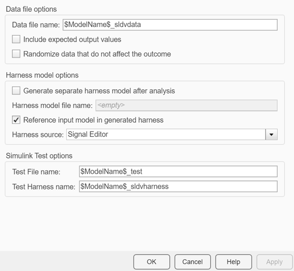
Specify options that control how Simulink® Design Verifier™ handles the results that it generates.
See Also
Data file name
Specify a folder and file name for the MAT file that contains the data generated during the
analysis, stored in an sldvData structure.
Settings
Default: $ModelName$_sldvdata
Optionally, enter a path that is either absolute or relative to the path name specified in Output folder.
Enter a file name for the MAT file.
$ModelName$is a token that represents the model name.
Command-Line Information
Parameter: DVDataFileName |
| Type: character array |
| Value: any valid path and file name |
Default: '$ModelName$_sldvdata' |
See Also
Include expected output values
Simulate the model using test case signals and include the output values in the Simulink Design Verifier data file.
Settings
Default: Off
 On
OnSimulates the model using the test case signals that the analysis produces. For each test case, the software collects the simulation output values associated with Outport blocks in the top-level system and includes those values in the MAT file that it generates.
 Off
OffDoes not simulate the model and collect output values for inclusion in the MAT file that the analysis generates.
Tips
The
TestCases.expectedOutputsubfield of the MAT file contains the output values. For more information, see Generate sldvData Structure.When Include expected output values is enabled, Simulink Design Verifier successively simulates the model using each test case that it generates. Enabling this option requires more time for Simulink Design Verifier to complete its analysis.
Command-Line Information
Parameter: DVSaveExpectedOutput |
| Type: character array |
Value: 'on' | 'off' |
Default: 'off' |
See Also
Randomize data that do not affect the outcome
Specify whether to use random values instead of zeros for input signals that have no impact on test or proof objectives.
Settings
Default: Off
- On
Assigns random values to test case or counterexample signals that do not affect the outcome of test or proof objectives in a model. This option can enhance traceability and improve your regression tests.
- Off
Assigns zeros to test case or counterexample signals that do not affect the outcome of test or proof objectives in a model.
Tips
This option replaces default data values with random values when the Simulink Design Verifier internal analysis engine does not specify a value. When a value does not influence the satisfaction of a test or proof objective, the generated analysis report indicates that value with a dash (–).
Simulink Design Verifier generated analysis reports show the setting of this option.
Enable this option to enhance traceability when simulating test cases or counterexamples. For instance, consider the following model:
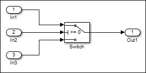
Only the signal entering the Switch block control port impacts its decision coverage. If the Randomize data that does not affect outcome parameter is off, Simulink Design Verifier uses zeros to represent the signals from In1 and In3. When inspecting the results from test case or counterexample simulations, it is unclear which of these signals passes through the Switch block because they have the same value. But if the Randomize data that does not affect outcome parameter is on, the software uses unique values to represent each of those signals. In this case, it is easier to determine which signal passes through the Switch block.
Command-Line Information
Parameter: DVRandomizeNoEffectData |
| Type: character array |
Value: 'on' | 'off' |
Default: 'off' |
See Also
Generate separate harness model after analysis
Create a harness model generated by the Simulink Design Verifier analysis.
Settings
Default: Off
- On
Saves the harness model that Simulink Design Verifier generates as a model file.
- Off
Does not save the harness model that Simulink Design Verifier generates.
Dependency
This parameter enables Harness model file name.
Command-Line Information
Parameter: DVSaveHarnessModel |
| Type: character array |
Value: 'on' | 'off' |
Default: 'off' |
See Also
Harness model file name
Specify a folder and file name for the harness model.
Settings
Default: $ModelName$_harness
Optionally, enter a path that is either absolute or relative to the path name specified in Output folder.
Enter a file name for the harness model.
$ModelName$is a token that represents the model name.
Dependency
This parameter is enabled by Generate separate harness model after analysis.
Command-Line Information
Parameter: DVHarnessModelFileName |
| Type: character array |
| Value: any valid path and file name |
Default: '$ModelName$_harness' |
See Also
Reference input model in generated harness
Use a Model block to reference the model to run in the harness model.
Settings
Default: On
- On
Uses a Model block to reference the model to run in the harness model.
- Off
Uses a copy of the model in the harness model.
Tips
If the Test Unit in the harness model is a subsystem, the values of the Simulink simulation optimization parameters on the Configuration Parameters dialog box can affect the coverage results.
Note
The simulation optimization parameters are on the following Configuration Parameters dialog box panes:
Optimization pane
Optimization > Signals and Parameters pane
Optimization > Stateflow pane
On the Design Verifier > Parameters pane, if you select the Apply parameters parameter, Simulink Design Verifier uses a subsystem that contains a copy of the original model in the harness model, even if you select Reference input model in generated harness.
Command-Line Information
Parameter: DVModelReferenceHarness |
| Type: character array |
Value: 'on' | 'off' |
Default: 'off' |
See Also
Test File Name
Name and path for test file name in Simulink Test™
Settings
Default: $ModelName$_test
Enter a file name for the test file containing Simulink Design Verifier results.
$ModelName$is a token that represents the model name.You can enter an absolute path, or a path relative to that specified by Output folder in the Design Verifier pane.
Dependency
This parameter is visible and enabled if you have a Simulink Test license.
Command-Line Information
Parameter: DVSlTestFileName |
| Type: character array |
| Value: any valid path and file name |
Default: '$ModelName$_test' |
See Also
Increase Coverage by Generating Test Inputs (Simulink Test)
Test Harness Name
Name of the test harness in Simulink Test
Settings
Default: $ModelName$_sldvharness
Enter a valid name for the test harness built to simulate Simulink Design Verifier test cases. The test harness corresponds to the test file specified by the parameter Test File name.
The
$ModelName$token represents the model name.Enter a valid MATLAB® identifier for the test harness name.
Dependency
This parameter is visible and enabled with a Simulink Test license.
Command-Line Information
Parameter: DVSlTestHarnessName |
| Type: character array |
| Value: any valid file name |
Default: '$ModelName$_sldvharness' |
See Also
Increase Coverage by Generating Test Inputs (Simulink Test)