Cable and Connectors
Libraries:
Simscape /
Electrical /
Connectors & References
Description
The Cable and Connectors block models a cable and connectors using resistors and inductors.
For most applications, you can directly connect two or more blocks with physical connection lines. These connection lines are idealized and have no resistance or inductance. If you need a simple physics-based model for an electrical cable or connectors, you can use a combination of Resistor blocks and Inductor blocks. Use the Cable and Connectors block instead if you want to:
Model multiple conductors in a single cable.
Analyze cables with open-circuit faults.
Analyze input or output connectors with short-circuit faults.
Parameterize the conductors by defining the material and geometry instead of the resistance and inductance.
Specify the gauge of the conductors using the American wire gauge (AWG) system.
Cable
The Cable and Connectors block models each conductor in the cable as a resistor. You can also choose to include an inductor in series with the resistor by selecting the Model cable inductance parameter. Clear this parameter to prioritize high simulation speeds. Select this parameter to prioritize accurate results.
To model a single conductor, clear the Model multiple conductors in cable parameter. To model multiple conductors, select the Model multiple conductors in cable parameter and specify the number of conductors using the Number of independent conductors in cable parameter.
The Cable and Connectors block has two ports that
represent the input and output ends of the cable. If you model a single conductor, these
In and Out ports are electrical conserving ports. If you model
multiple conductors, the In and Out ports are electrical
array-of-nodes conserving ports. To connect the electrical array-of-nodes ports to the rest
of your network, use an Array
Connection block to act as a multiplexor for the Simscape™ electrical domain by concatenating all input array of nodes into a single 1-D
array. First, connect the In and Out ports to the
RConn ports of separate Array Connection
blocks. The RConn port name is not visible in the block icon, but you can see
this name if you pause your pointer over the port. Then, set the Domain
parameter of the Array Connection block to
Electrical Domain. Finally, set the Number of scalar
elements parameter of the Array Connection
blocks to the same value as the Number of independent conductors in
cable parameter of the Cable and Connectors
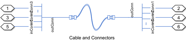
block. This figure shows how to connect a Cable and
Connectors block with three independent conductors in the cable to an
electrical network.
The block assumes that the conductors in the cable are round wires and calculates the resistance of each conductor, R, using these equations [1],
where:
ρ is the electrical resistivity of each conductor.
L is the value of the Length of conductor parameter.
r is the radius of the conductor.
δ is the skin depth.
μ is the magnetic permeability of the conductor.
σ is the specific conductivity of the conductor.
f is the rated frequency.
For DC current, there is no skin effect. The current spreads evenly over the cross-section of the conductor, so δ = r. For high-frequency AC current, at full skin effect, current flows only on the surface of the conductor, so δ = 0.
If you clear the Model skin effect parameter, f = 0. If you select the Model skin effect parameter, f is equal to the value of the Rated frequency parameter.
If you select the Model cable inductance parameter, the block calculates the inductance of each conductor LDC using these equations [2],
where:
μ0 is the permeability of free space.
Y is the current distribution constant.
The current distribution constant has a value between 0 and 1. For DC, Y = 1. For high-frequency AC, Y approaches 0.
Connectors
The block models the connectors with resistors. The number of pins in the conductor is
equal to the number of independent conductors in the cable. This figure shows the equivalent
circuit for a three-pin input connector. The resistors labeled Ri model
the contact resistance between each pin and the corresponding socket. The resistors labeled
Gij model the inter-pin conductance for each pin pair
(i,j).
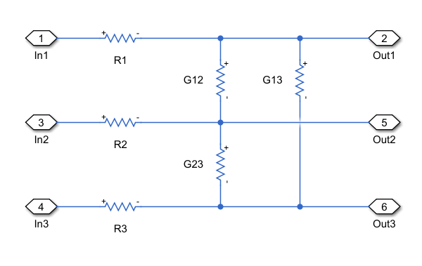
Specify the resistance of resistors Ri using the Contact
resistance between pin and sockets parameter. Specify the conductance of
resistors Gij using the Conductance between pins
parameter.
You do not always need to model connectors at both ends of the cable. For example:
If you model a cable soldered directly to a printed circuit board (PCB), then do not model the connector at that end of the cable, for greater accuracy.
If you model a cable with almost ideal connectors, or if you model an open-circuit fault in the cable, the inter-pin conductance and the contact resistance between the pins and sockets in the connectors have a negligible impact on the simulation results.
You can choose whether to model each connector by using the Model input connector and Model output connector parameters. To increase the simulation speed, do not model the connectors if you do not need to.
Faults
To model a fault in the Cable and Connectors block, in the Faults section, click Add fault next to the fault that you want to model. For more information about fault modeling, see Fault Behavior Modeling and Fault Triggering.
The Cable and Connectors block models electrical faults as an instantaneous change in the conductance of the cable or connectors. You can model an open-circuit fault in the cable or a short-circuit fault in the connectors.
When the cable fails in open circuit, the conductance of the conductors changes to the value of the Open-circuit conductance parameter. If you model multiple conductors in the same cable, you can choose to trigger faults for all conductors or specify which conductors you want to fail.
To trigger an open-circuit fault for all conductors, set Faultable conductors to
Make all conductors faultable.To trigger an open-circuit fault for specific conductors, set Faultable conductors to
Specify faultable conductorsand specify which conductors you want to fail using the Indices of faultable conductors parameter.
When an input or output connector short circuits, the inter-pin conductance of pin pairs changes to the value of the Short-circuit conductance of faulted input connector or Short-circuit conductance of faulted output connector parameter, respectively.
To trigger a short-circuit fault for all pin pairs, set Faultable pin pairs to
Make all pin pairs faultable.To trigger a short-circuit fault for specific pin pairs, set Faultable conductors to
Specify faultable conductorsand specify which conductors you want to fail using the Matrix of faultable pin pairs parameter. Each row of this matrix defines a pair of pins by their indices. For example, to enable a short-circuit fault between pin 1 and pin 2, add the row1,2;to the matrix.
You can specify how and when faults occur by using the Trigger type parameter.
If you set the Trigger type to
Behavioral, the Cable and Connectors block triggers fault events when
the temperature continuously exceeds the value of the Maximum permissible
temperature for a duration longer than the value of the Time to
fail when exceeding temperature parameter. The block also triggers:
Open-circuit faults in the cable when the current continuously exceeds the value of the Maximum permissible current parameter for a duration longer than the value of the Time to fail when exceeding current parameter.
Short-circuit faults in the connectors when the voltage continuously exceeds the value of the Maximum permissible voltage parameter for a duration longer than the value of the Time to fail when exceeding voltage parameter.
If you set the Trigger
type to Conditional, you can choose whether faults
in the Cable and Connectors block are reversible (since R2025a). To model irreversible faults, click
Open fault properties to open the Property Inspector and select the
Trigger stays on once activated parameter. The block enters the faulted
state when the trigger condition becomes true for the first time and remains in the faulted
state for the rest of the simulation. To model reversible faults, clear the Trigger
stays on once activated parameter. The block enters the faulted state when the
trigger condition is true and enters the unfaulted state when the trigger condition is
false.
For more information about adding faults to blocks and specifying fault triggers, see Introduction to Simscape Faults.
Examples
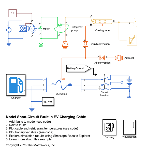
Model Short-Circuit Fault in EV Charging Cable
Model and prevent a short-circuit fault in the connectors of an electric vehicle (EV) charging cable. First, you examine the system under normal operating conditions with effective refrigerant cooling and a constant-current (CC), constant-voltage (CV) charging strategy. Then, you introduce an open-circuit fault in the motor of the refrigeration system. This fault causes the cable to overheat, resulting in the short-circuit fault in the cable connectors. Finally, you regulate the current to enable passive cooling and safer battery charging without relying only on the refrigeration system.
Ports
Conserving
Parameters
References
[1] Keller, Reto B. “Skin Effect.” In Design for Electromagnetic Compatibility--In a Nutshell, by Reto B. Keller, 135–43. Cham: Springer International Publishing, 2023. https://doi.org/10.1007/978-3-031-14186-7_10.
[2] Rosa, E. B. “The Self and Mutual Inductances of Linear Conductors.” In Bulletin of the Bureau of Standards 4, no. 2 (January 1908): 301. https://doi.org/10.6028/bulletin.088.