Unipolar Stepper Motor Driver
Driver for unipolar stepper motor
Libraries:
Simscape /
Electrical /
Electromechanical /
Reluctance & Stepper
Description
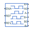
The Unipolar Stepper Motor Driver block represents a driver specifically configured for use with the Unipolar Stepper Motor block. It connects the two winding center-tap connections A0 and B0 to the positive supply with a voltage equal to the value you provide for the Output voltage amplitude parameter. The A+, A-, B+, and B- ports are grounded in the appropriate sequence to create the stepping motion. The block initiates a step each time the voltage at the ENA port rises above the Enable threshold voltage parameter value.
If the voltage at the REV port is less than or equal to the Reverse threshold voltage parameter value, pulse A leads pulse B by 90 degrees. If the voltage at the REV port is greater than the Reverse threshold voltage value, pulse B leads pulse A by 90 degrees and the motor direction is reversed.
At time zero, A- and B+ are grounded.
If you set the Stepping mode parameter to Half
stepping, the Unipolar Stepper Motor
Driver block can produce the output waveforms required for half
stepping. In this mode, there is an intermediate state between the full steps, in which
just one of the A or the B half-windings is
powered. As a result, the step size is half of the stepper motor’s full step size. At
half steps, windings that are not powered are short-circuited. This approximates the
effect of a freewheeling diode connected across the windings.
Averaged Mode
If you set the Simulation mode parameter to
Averaged, both for a Unipolar Stepper
Motor Driver block and for the Unipolar Stepper
Motor block connected to it, then the individual steps are not
simulated. This can be a good way to speed up simulation. The
Averaged mode assumes that the external controller
provides a step rate demand. This step rate demand is determined from the voltage
applied between the ENA and REF ports on
the Unipolar Stepper Motor Driver block, by
multiplying this voltage by the value of the Step rate
sensitivity parameter. The rotation direction is set by the
REF port in the same way as for the Stepping mode.
Averaged mode needs to communicate the step rate demand
and also output voltage amplitude information to the Unipolar Stepper
Motor block. To do this, the step rate demand is applied as an
equivalent voltage across the A+ and A-
ports. Similarly the output voltage amplitude information is conveyed by applying a
steady-state voltage across the B+ and B-
ports with value equal to the Output voltage amplitude
parameter.
Examples

Unipolar Stepper Motor with Control
Model a controlled permanent magnet stepper motor by using the Unipolar Stepper Motor and Unipolar Stepper Motor Driver blocks. The model has two controller options: one to control position and one to control speed. To change the controller type, right-click the Controller subsystem, select Variant > Label Mode Active Choice, and then select Position or Speed. The stepper has a full step size of 1.8 degrees. In position control mode, the input to the Ref port is the desired number of steps. In speed control mode, the input to the Ref port is the desired number of steps per second.

Unipolar Stepper Motor Averaged Mode
The Unipolar Stepper Motor simulating in Stepping and Averaged simulation modes. The purpose of Averaged mode is faster simulation for any loads that do not cause slip. To avoid incorrect interpretation of results, the stepper motor has an approximate detection of slip which can be set to generate a warning or an error.
Assumptions and Limitations
To use
Averagedmode, the Unipolar Stepper Motor Driver block must be directly connected to a Unipolar Stepper Motor block also running in Averaged mode.When changing from Stepping to Averaged mode and back, you will need to modify your upstream blocks that provide the input voltages to the Unipolar Stepper Motor Driver. One way to achieve this easily is to use Simulink® variant subsystems.
Ports
Conserving
Parameters
Extended Capabilities
Version History
Introduced in R2014a