Creazione di un modello di architettura con interfacce e collegamenti ai requisiti
In questo argomento, è possibile scoprire come creare un modello di architettura di un braccio robotico utilizzando System Composer™, definire interfacce sulle porte e aggiungere collegamenti ai requisiti nei componenti.
Scoprire come:
Avviare System Composer.
Aggiungere componenti architetturali per rappresentare i sensori del braccio robotico, la pianificazione della traiettoria e il suo movimento.
Creare porte e collegamenti per rappresentare lo scambio di dati.
Definire le interfacce dati per rappresentare la struttura dei dati.
Gestire i collegamenti ai requisiti per rappresentare i collegamenti ai requisiti dagli elementi del modello.
È necessaria una licenza Requirements Toolbox™ per collegare, tracciare e gestire i requisiti in System Composer.
Per maggiori informazioni sul workflow di ingegneria dei sistemi Model-Based in System Composer, vedere Composizione e analisi dei sistemi utilizzando modelli di architettura.
Rappresentazione visiva del sistema
L'implementazione di un progetto architetturale inizia con la rappresentazione visiva del sistema utilizzando i componenti e le loro collegamenti. Creare un modello di architettura, rappresentare i componenti del sistema e disegnare i collegamenti tra gli stessi.
Creazione di un modello di architettura
Inserire questo comando nella finestra di comando MATLAB®.
systemcomposer
La pagina iniziale di Simulink® si apre su System Composer.
Fare clic su Architecture Model.
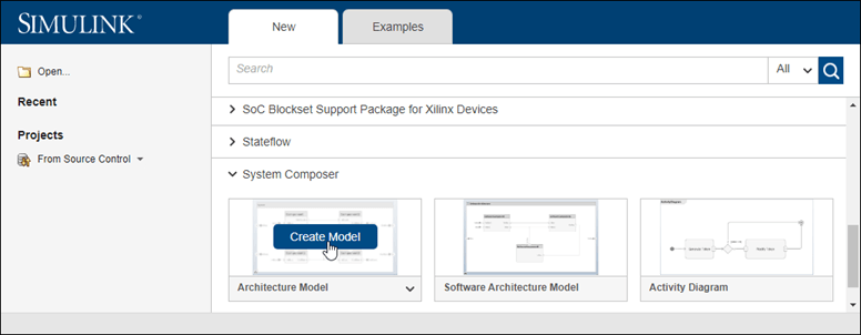
System Composer fornisce modelli di architettura template che coprono diversi ambiti nell'ingegneria dei sistemi e nella modellazione dell'architettura software: Architecture Model e Software Architecture Model. Tutti i modelli di architettura offrono le stesse funzionalità strutturali con alcune limitazioni specifiche relative al dominio e alla piattaforma. Per maggiori informazioni sui template di architettura, vedere Choose Architecture Template for System Design.
Si apre una nuova area di disegno vuota del modello di architettura. È possibile identificare un modello di architettura tramite il badge nell'angolo inferiore sinistro e la tavolozza dei componenti sul lato sinistro.

Fare doppio clic sull'intestazione del modello di architettura e modificare
untitledcon un nome descrittivo del modello, ad esempioRobotDesign. In genere, il nome del modello riflette il sistema di cui si sta costruendo l'architettura.
Salvare il modello.
Disegno dei componenti
Progettare un braccio robotico mobile in cui un sensore rileva la posizione e la pianificazione della traiettoria calcola un percorso verso una posizione che il robot deve raggiungere utilizzando il movimento. Un modello di architettura di un sistema di questo tipo potrebbe essere costituito da tre componenti principali: Sensors, Trajectory Planning e Motion. È possibile rappresentare questi componenti in System Composer utilizzando tre blocchi Component.
Fare clic e trascinare un blocco Component
 dalla tavolozza sul lato sinistro.
Rinominare il componente come
Sensors.Seguire queste fasi per creare i componenti
Trajectory PlanningeMotion.
Creazione di porte e collegamenti
È possibile iniziare a creare la connettività tra i componenti descrivendo il flusso di potenza, energia, dati o qualsiasi altra informazione rappresentativa. Creare porte sui componenti che forniscono o consumano informazioni e connettori che collegano due porte dei componenti per rappresentare il flusso delle informazioni.
È possibile aggiungere una porta a un componente su qualsiasi lato e la porta può avere una direzione di input o di output. Per creare una porta, soffermarsi con il cursore su un lato del componente. Fare clic e rilasciare per visualizzare le opzioni della porta. Selezionare Input, Output o Physical per creare una porta. Rinominare la porta utilizzando un nome che rappresenti le informazioni che fluiscono attraverso quella porta.
Creare una porta di output nella parte inferiore del componente Sensors (Sensori). Rinominarlo SensorData.

Fare clic e trascinare una linea dalla porta di output SensorData al componente
Motion. Quando si visualizza una porta di input creata sul lato del componente, rilasciare il puntatore. Per impostazione predefinita, questa nuova porta ha lo stesso nome della porta sorgente.Soffermarsi sull'angolo della linea SensorData finché non appare l'icona di diramazione
 . Fare clic con il tasto destro del mouse e trascinare una linea di diramazione sul componente
 Trajectory Planning.
Completare i collegamenti come mostrato in questa figura.

Il livello radice del modello di architettura può anche avere porte che descrivono l'interazione del sistema con il suo ambiente. In questo esempio, la posizione di destinazione del robot è fornita da un computer esterno al robot stesso. Rappresentare questa relazione con una porta di input.
Fare clic sul bordo sinistro del modello di architettura e inserire il nome della porta TargetPosition.
Collegare una porta di architettura a un componente trascinando una linea dalla porta di input TargetPosition al componente
Trajectory Planning. I collegamenti da una porta di architettura o verso di essa vengono visualizzati come tag.
Modifica delle interfacce dati
È possibile definire un'interfaccia dati per specificare completamente un collegamento e le porte associate. Un'interfaccia dati può essere costituita da più elementi dati con varie dimensioni, unità e tipi di dati. Per verificare la coerenza quando si collega una porta, è inoltre possibile associare le interfacce alle porte non collegate durante la progettazione dei componenti.
Specificare il flusso di informazioni attraverso una porta tra i componenti configurando l'interfaccia dati con gli attributi. Un'interfaccia dati può essere semplice come l'invio di un valore intero, ma può anche essere un insieme di numeri, un'enumerazione, una combinazione di numeri e stringhe o un raggruppamento di altre interfacce predefinite.
Considerare l'interfaccia dati tra i componenti Sensors e Motion. I dati del sensore sono costituiti da:
Dati di posizione da due motori
Dati sulla vicinanza degli ostacoli rilevati da due sensori
Un timestamp per indicare l'attualità dei dati
Per aprire Interface Editor, andare a Modeling > Interface Editor.
Fare clic sul pulsante
 per aggiungere un'interfaccia dati. Assegnare un nome all'interfaccia
 sensordata.L'interfaccia dati viene denominata e definita separatamente rispetto a una porta del componente e quindi assegnata a una porta.
Fare clic sulla porta di output SensorData sul componente
Sensors. In Interface Editor, fare clic con il tasto destro del mouse susensordatae selezionare Assign to Selected Port(s).Se si fa nuovamente clic su
sensordata, le tre porte SensorData vengono evidenziate, indicando che le porte collegate sono associate a tale interfaccia.
Aggiungere un elemento dati all'interfaccia dati selezionata. Fare clic sul pulsante
 per aggiungere un elemento dati e denominarlo
 timestamp.Continuare ad aggiungere elementi dati all'interfaccia dati come specificato, facendo clic sul pulsante Add data element (Aggiungi elemento dati).
Nome Tipo Unità timestampdoublesecondsdirection1doubledegreesdirection2doubledegreesdistance1doublemetersdistance2doublemetersposition1doubledegreesposition2doubledegreesModificare le proprietà di un elemento dati in Interface Editor. Fare clic sulla cella corrispondente all'elemento dati nella tabella e aggiungere le unità come indicato nella specifica.
Fare clic sull'elenco a discesa accanto al pulsante
 per salvare l'interfaccia dati in un dizionario dei dati. Un dizionario dei dati consente di gestire collettivamente e condividere un insieme di interfacce tra i modelli. Ad esempio, se in una fase successiva della progettazione, si sceglie di modellare il computer esterno come un modello di architettura separato, questo modello e il modello
 Robotpossono condividere lo stesso dizionario dei dati. In questo caso, il dizionario è salvato comeRobotDD.
Scomposizione dei componenti
Ogni componente può avere una propria architettura. Fare doppio clic su un componente per scomporlo nei suoi sottocomponenti.
Fare doppio clic sul componente
Trajectory Planning. La barra Explorer e Model Browser indicano la posizione del componente nella gerarchia del modello.
Questo componente utilizza innanzitutto i dati di posizione del motore che fanno parte dell'interfaccia
sensordataper calcolare il comando ideale di posizione e velocità. Quindi elabora le informazioni sulla distanza dagli ostacoli contenute nella stessa interfaccia per adeguare il comando di movimento in base ad alcune regole di sicurezza.Aggiungere i componenti
Motion ControleSafety Rulescome parte dell'architetturaTrajectory Planning.Trascinare la porta TargetPosition sul componente
Motion Control. Aggiungere una porta di output Command aMotion Control, quindi trascinare una linea al componentSafety Rules. Trascinare le linee dalla porta SensorData ai componentiMotion ControleSafety Rules.
Modello di architettura del braccio robotico
Aprire il modello di architettura di un braccio robotico composto da sensori, attuatori di movimento e un algoritmo di pianificazione. È possibile utilizzare System Composer per visualizzare le interfacce e gestire i requisiti per questo modello.

Gestione dei collegamenti ai requisiti
I requisiti sono parte integrante del processo di ingegneria dei sistemi. Alcuni requisiti riguardano la funzionalità del sistema nel suo complesso, mentre altri riguardano aspetti relativi alle prestazioni quali potenza, dimensioni e peso. Scomporre i requisiti di alto livello in requisiti di basso livello e derivare ulteriori requisiti è fondamentale per definire l'architettura dell'intero sistema. Ad esempio, il consumo energetico complessivo del robot determina il fabbisogno relativo al consumo energetico del controller del robot.
Per allocare e tracciare i requisiti con gli elementi di sistema, System Composer si integra completamente con Requirements Toolbox. Per derivare requisiti appropriati, è talvolta necessario analizzare e specificare le proprietà (come la potenza) degli elementi del sistema, inclusi componenti, porte o connettori. Ad esempio, se il costo totale del sistema rappresenta un fattore critico, è necessaria una proprietà unitPrice.
Gestire i requisiti alla Prospettiva dei requisiti in System Composer utilizzando Requirements Toolbox. Andare a Apps > Requirements Manager. Per maggiori informazioni, vedere Visualizzazione e collegamento dei requisiti in Simulink (Requirements Toolbox).

Per migliorare la tracciabilità dei requisiti, collegare i requisiti ai componenti architetturali e alle porte. Quando si fa clic su un componente nella Prospettiva dei requisiti, vengono evidenziati i requisiti collegati. Al contrario, quando si fa clic su un requisito, vengono visualizzati i componenti collegati. Per creare direttamente un collegamento, trascinare un requisito su un componente o una porta.
Vedi anche
Argomenti
- Estensione della progettazione architetturale utilizzando gli stereotipi
- Analisi delle proprietà del modello di architettura con la funzione di analisi
- Esame dei componenti nelle viste dell'architettura personalizzata
- Implementazione di comportamenti per la simulazione di modelli di architettura
- Concetti di System Composer