Concetti di System Composer
System Composer™ unisce concetti di ingegneria dei sistemi con concetti di Simulink®. Questa pagina definisce tali concetti e le rispettive applicazioni per aiutare a comprendere in che modo questi domini si sovrappongano. Utilizzare questa pagina per imparare i concetti rilevanti e come si applicano alla progettazione ingegneristica dei sistemi. Ogni sezione definisce un concetto e spiega come viene utilizzato in System Composer; fornisce inoltre collegamenti a ulteriori informazioni nella documentazione.
Creazione di modelli per descrivere la struttura delle architetture di sistema e software
Creare comportamenti fisici per i componenti utilizzando Simscape
Descrizione delle specifiche delle porte utilizzando le interfacce
Estensione del linguaggio di modellazione dell'architettura con profili e stereotipi
Rappresentazione di alternative di progettazione utilizzando componenti con varianti
Utilizzo dell'analisi per eseguire studi comparativi e validare le architetture rispetto ai vincoli
Strutturazione delle architetture complesse in diagrammi più semplici creando viste filtrate
Simulazione dell'architettura integrata implementando i comportamenti dei componenti
Specifica dei vincoli operativi tra i componenti utilizzando diagrammi di sequenza eseguibili
Creazione e simulazione di diagrammi di attività da allocare ai componenti
Creazione, simulazione e distribuzione di architetture software
In base all'obiettivo di modellazione architetturale, consultare la sezione corrispondente per saperne di più sui concetti chiave associati a tale obiettivo.
Creazione di modelli per descrivere la struttura delle architetture di sistema e software
"Creare modelli di architettura in System Composer per modellare e descrivere il sistema di sistemi.
| Termine | Definizione | Applicazione | Maggiori informazioni |
|---|---|---|---|
| Architettura | Un'architettura System Composer rappresenta un sistema di componenti e il modo in cui tali componenti si interfacciano tra loro dal punto di vista strutturale e comportamentale. | Diversi tipi di architetture descrivono diversi aspetti dei sistemi. È possibile utilizzare le viste per visualizzare un sottoinsieme di componenti in un'architettura. È possibile definire i parametri a livello di architettura utilizzando Parameter Editor. | |
| Radice | Una radice si trova al vertice di una gerarchia dell'architettura. Un'architettura radice ha un confine definito dalle porte di architettura che circondano il sistema di interesse. | L'architettura radice presenta un confine di sistema che circonda il modello di architettura. È possibile aggiungere porte di architettura che definiscono le interfacce attraverso il confine. | |
| Modello | Un modello di System Composer è il file che contiene le informazioni architetturali, quali componenti, porte, connettori, interfacce e comportamenti. | Eseguire operazioni su un modello, tra cui l'estrazione dell'architettura di livello radice, l'applicazione di profili, il collegamento di dizionari dei dati dell'interfaccia o la generazione di istanze dall'architettura del modello. Un modello di System Composer viene memorizzato come file .slx. | Creazione di un modello di architettura con interfacce e collegamenti ai requisiti |
| Componente | Un componente è una parte sostituibile di un sistema che svolge una funzione chiara nel contesto di un'architettura. Un componente definisce un elemento architetturale, come una funzione, un altro sistema, hardware, software o altra entità concettuale. Un componente può anche essere un sottosistema o una funzione secondaria. | Un componente, che è rappresentato come un blocco, è una parte di un modello di architettura che può essere separato in artefatti riutilizzabili. Trasferire le informazioni tra i componenti con interfacce di porta utilizzando Interface Editor e i parametri utilizzando Parameter Editor. | |
| Porta | Una porta è un nodo su un componente o un'architettura che rappresenta un punto di interazione con il suo ambiente. Una porta consente il flusso di informazioni da e verso altri componenti o sistemi. | Le porte dei componenti sono punti di interazione del componente con altri componenti. Le porte di architettura sono porte situate al confine del sistema, sia che il confine si trovi all'interno di un componente sia nel modello di architettura complessivo. L'architettura radice ha un confine definito dalle sue porte. | |
| Connettore | I connettori sono linee che forniscono collegamenti tra le porte. I connettori descrivono come le informazioni fluiscono tra componenti o architetture. | Un connettore consente a due componenti di interagire senza definire la natura dell'interazione. Impostare un'interfaccia su una porta per definire come interagiscono i componenti. |
Creare comportamenti fisici per i componenti utilizzando Simscape
Creare modelli fisici in System Composer utilizzando componenti del sottosistema. Un componente del sottosistema è un sottosistema di Simulink che fa parte del modello di architettura principale di System Composer. Le informazioni fisiche possono estendersi oltre i confini dei componenti del sottosistema. È possibile descrivere i componenti fisici con porte fisiche, connettori e interfacce. Utilizzare i blocchi Simscape™ per descrivere il comportamento di tali componenti fisici.
| Termine | Definizione | Applicazione | Maggiori informazioni |
|---|---|---|---|
| Sottosistema fisico | Un sottosistema fisico è un sottosistema di Simulink con collegamenti Simscape. | Un sottosistema fisico con collegamenti Simscape utilizza un approccio di rete fisica adatto alla simulazione di sistemi con componenti fisici reali e rappresenta un modello matematico. | Implement Component Behavior Using Simscape |
| Porta fisica | Una porta fisica rappresenta una porta connettore di modellazione fisica Simscape denominata Connection Port (Simscape). | Utilizzare le porte fisiche per collegare i componenti in un modello di architettura o per abilitare i sistemi fisici in un sottosistema di Simulink. | Define Physical Ports on Component |
| Connettore fisico | Un connettore fisico può rappresentare un collegamento conservativo non direzionale di un dominio fisico specifico. I connettori possono anche rappresentare segnali fisici. | Utilizzare i connettori fisici per collegare componenti fisici che rappresentano le feature di un sistema da simulare matematicamente. | Architecture Model with Simscape Behavior for a DC Motor |
| Interfaccia fisica | Un'interfaccia fisica definisce il tipo di informazioni che fluiscono attraverso una porta fisica. La stessa interfaccia può essere assegnata a più porte. Un'interfaccia fisica è un'interfaccia composita equivalente a un oggetto | Utilizzare un'interfaccia fisica per raggruppare elementi fisici e descrivere un modello fisico utilizzando almeno un dominio fisico. | Specify Physical Interfaces on Ports |
| Elemento fisico | Un elemento fisico descrive la scomposizione di un'interfaccia fisica. Un elemento fisico è equivalente a un oggetto | Definire il | Describe Component Behavior Using Simscape |
Descrizione delle specifiche delle porte utilizzando le interfacce
Definire le interfacce per rappresentare il tipo di informazioni che fluiscono attraverso una porta. Assegnare le interfacce alle porte utilizzando Interface Editor in Dictionary View. Utilizzare un blocco Adapter per riconciliare le differenze tra le interfacce su un connettore tra porte.
Gestire le interfacce di proprietà locali a una porta utilizzando Interface Editor in Port Interface View.
| Termine | Definizione | Applicazione | Maggiori informazioni |
|---|---|---|---|
| Dizionario dei dati | Un dizionario dei dati è un repository di dati rilevanti per il modello. La sezione Architectural Data (Dati architetturali) di un dizionario dei dati memorizza le definizioni condivise utilizzate nelle interfacce di Simulink e dei modelli di architettura, quali interfacce di porta, tipi di dati e costanti a livello di sistema. Per maggiori informazioni, vedere What Is a Data Dictionary? | È possibile salvare le interfacce locali su un modello di System Composer nella sezione Architectural Data (Dati architetturali) di un dizionario dei dati di Simulink utilizzando Interface Editor. Oltre a Interface Editor, è anche possibile utilizzare Architectural Data Editor per gestire e modificare le interfacce e i tipi di valori. | |
| Interfaccia dati | Un'interfaccia dati definisce il tipo di informazioni che fluiscono attraverso una porta. La stessa interfaccia può essere assegnata a più porte. Un'interfaccia dati può essere composita, ossia può includere elementi dati che descrivono le proprietà di un segnale di interfaccia. | Le interfacce dati rappresentano le informazioni condivise tramite un connettore e che entrano o escono da un componente tramite una porta. Utilizzare Interface Editor per creare e gestire interfacce dati ed elementi dati e memorizzarli in un dizionario dei dati per riutilizzarli tra i modelli. | |
| Elemento dati | Un elemento dati descrive una parte di un'interfaccia, come un messaggio di comunicazione, un parametro calcolato o misurato o altra scomposizione di tale interfaccia. | Le interfacce dati sono scomposte in elementi dati che possono rappresentare pin o cavi in un connettore o harness, messaggi trasmessi attraverso un bus e strutture di dati condivise tra i componenti. | |
| Tipo di valore | Un tipo di valore può essere utilizzato come interfaccia di porta per definire l'unità atomica di dati che fluisce attraverso quella porta e presenta un tipo di primo livello, una dimensione, un'unità, una complessità, un valore minimo, un valore massimo e una descrizione. | È inoltre possibile assegnare il tipo di elementi dati nelle interfacce dati ai tipi di valore. Aggiungere i tipi di valore ai dizionari dei dati utilizzando Interface Editor in modo da poterli riutilizzare come interfacce o elementi dati. | Create Value Types as Interfaces |
| Interfaccia di proprietà | Un'interfaccia di proprietà è un'interfaccia locale a una porta specifica e non condivisa in un dizionario dei dati o nel dizionario del modello. | Creare un'interfaccia di proprietà per rappresentare un tipo di valore o un'interfaccia dati locale a una porta. | Define Owned Interfaces Local to Ports |
| Adattatore | Un adattatore collega due componenti con interfacce di porta incompatibili mappando le due interfacce. Un adattatore può fungere da ritardo unitario, transizione di velocità o unione. È inoltre possibile utilizzare un adattatore per la creazione di bus. Utilizzare il blocco Adapter per implementare un adattatore. | Con un adattatore, nella finestra di dialogo Interface Adapter, è possibile: creare e modificare le mappature tra interfacce di input e di output, applicare una conversione di interfaccia |
Estensione del linguaggio di modellazione dell'architettura con profili e stereotipi
Creare un profilo in Profile Editor e aggiungere degli stereotipi con proprietà. Applicare lo stereotipo a un componente e impostare il valore della proprietà in Property Inspector.
| Termine | Definizione | Applicazione | Maggiori informazioni |
|---|---|---|---|
| Stereotipo | Gli stereotipi forniscono un meccanismo per estendere gli elementi linguistici di base e aggiungere metadati specifici del dominio. | Applicare gli stereotipi ai tipi di elementi di base. Un elemento può avere più stereotipi. Gli stereotipi consentono di definire lo stile di diversi elementi. Gli stereotipi forniscono elementi con un insieme di proprietà comuni, quali massa, costo e potenza. | |
| Proprietà | Una proprietà è un campo in uno stereotipo. È possibile specificare i valori delle proprietà per ciascun elemento a cui è applicato lo stereotipo. | Utilizzare le proprietà per memorizzare caratteristiche quantitative, quali peso o velocità, associate a un elemento del modello. Le proprietà possono anche essere descrittive o rappresentare uno stato. È possibile visualizzare e modificare le proprietà di ciascun elemento nel modello di architettura utilizzando Property Inspector. Per maggiori informazioni, vedere Use Property Inspector in System Composer. | |
| Profilo | Un profilo è un pacchetto di stereotipi. | È possibile utilizzare i profili per creare un dominio di tipi di elementi specializzati. Creare profili e applicarli a un modello utilizzando Profile Editor. È possibile memorizzare gli stereotipi per un progetto in uno o più profili. Quando si salvano i profili, questi vengono memorizzati in file .xml. |
Rappresentazione di alternative di progettazione utilizzando componenti con varianti
Creare componenti con varianti e implementare più alternative di progettazione o di varianti, scelte in base a regole programmatiche. Aggiungere scelte di variante a un componente per creare un componente con varianti. La scelta attiva rappresenta il componente originale.
| Termine | Definizione | Applicazione | Maggiori informazioni |
|---|---|---|---|
| Variante | Una variante è una delle molte scelte strutturali o comportamentali disponibili in un componente con varianti. | Utilizzare le varianti per sostituire rapidamente diversi progetti architetturali per un componente durante l'esecuzione dell'analisi. | Create Variants (Creazione di varianti) |
| Controllo delle varianti | Un controllo delle varianti è una stringa che controlla la scelta della variante attiva. | Impostare il controllo delle varianti in modo programmatico per controllare quale variante è attiva. | Set Variant Control Condition |
Utilizzo dell'analisi per eseguire studi comparativi e validare le architetture rispetto ai vincoli
Creare una funzione di analisi per analizzare il consumo energetico nel modello di architettura RobotDesign.
function RobotDesign_1(instance,varargin)

if instance.isComponent() && ~isempty(instance.Components) ...
&& instance.hasValue('RobotProfile.ElectricalComponent.Power')
    sysComponent_power = 0;
    for child = instance.Components
        if child.hasValue('RobotProfile.ElectricalComponent.Power')
           comp_power = child.getValue('RobotProfile.ElectricalComponent.Power');
           sysComponent_power = sysComponent_power + comp_power;
           instance.setValue('RobotProfile.ElectricalComponent.Power', ...
           sysComponent_power);
        end
    end
end
Analizzare il progetto del robot utilizzando la funzione di analisi per determinare il consumo energetico totale.
| Termine | Definizione | Applicazione | Maggiori informazioni |
|---|---|---|---|
| Analisi | L'analisi statica analizza la struttura del sistema per valutare quantitativamente un'architettura rispetto a determinate caratteristiche. L'analisi statica utilizza una funzione di analisi e valori parametrici delle proprietà e dei parametri acquisiti nel modello di sistema. | Utilizzare le analisi per calcolare l'affidabilità complessiva, la somma delle masse, le prestazioni o le caratteristiche termiche di un sistema, oppure per eseguire un'analisi delle dimensioni, del peso e della potenza (SWaP) al fine di aumentare l'efficienza. | |
| Funzione di analisi | Una funzione di analisi è una funzione di MATLAB® è una funzione che calcola i valori necessari per valutare l'architettura utilizzando le proprietà di ciascun elemento nell'istanza del modello e i parametri specifici dell'istanza a livello di componente e di architettura. | Utilizzare una funzione di analisi per calcolare il risultato di un'analisi. | |
| Modello di istanza | Un modello di istanza è una raccolta di istanze. | È possibile aggiornare un modello di istanza con le modifiche apportate a un modello, ma il modello di istanza non verrà aggiornato con le modifiche apportate alle varianti attive o ai riferimenti al modello. È possibile utilizzare un modello di istanza, salvato in un file | Run Analysis Function |
| Istanza | Un'istanza è un'occorrenza di un elemento del modello di architettura in un dato punto nel tempo. | Un'istanza blocca la variante attiva o il riferimento al modello del componente nel modello dell'istanza. | Create a Model Instance for Analysis |
Definizione delle relazioni tra elementi di diversi modelli di architettura utilizzando le allocazioni
In Allocation Editor, allocare i componenti tra due modelli di architettura, in base a una dipendenza o a una relazione direzionale.
| Termine | Definizione | Applicazione | Maggiori informazioni |
|---|---|---|---|
| Allocazione | Un'allocazione stabilisce una relazione direzionale tra elementi architetturali (componenti, porte e connettori) di un modello e gli elementi architetturali di un altro modello. | L'allocazione basata sulle risorse consente di allocare elementi architetturali funzionali a elementi architetturali logici ed elementi architetturali logici a elementi architetturali fisici. | |
| Scenario di allocazione | Uno scenario di allocazione contiene un insieme di allocazioni tra un modello sorgente e un modello di destinazione. | Allocare tra gli elementi del modello in uno scenario di allocazione. Lo scenario di allocazione predefinito è denominato | Systems Engineering Approach for SoC Applications |
| Insieme di allocazioni | Un insieme di allocazioni è costituito da uno o più scenari di allocazione che descrivono varie allocazioni tra un modello sorgente e un modello di destinazione. | Creare un insieme di allocazioni con scenari di allocazione in Allocation Editor. Gli insiemi di allocazione vengono salvati come file .mldatx. |
Strutturazione delle architetture complesse in diagrammi più semplici creando viste filtrate
Applicare un filtro di visualizzazione per generare un gruppo di elementi di componenti per la vista in Architecture Views Gallery.
| Termine | Definizione | Applicazione | Maggiori informazioni |
|---|---|---|---|
| Vista | Una vista mostra un sottoinsieme personalizzabile di elementi in un modello. Le viste possono essere filtrate in base a stereotipi o nomi di componenti, porte e interfacce, insieme al nome, al tipo o alle unità di un elemento dell'interfaccia. Creare le viste aggiungendo manualmente gli elementi. Le viste creano un modo semplificato per lavorare con architetture complesse concentrandosi su determinate parti della progettazione architetturale. | È possibile utilizzare diversi tipi di viste per rappresentare il sistema. Commutare da un diagramma dei componenti, alla gerarchia dei componenti o alla gerarchia dell'architettura. Per le architetture software, è possibile passare a una vista a diagramma delle classi. Un punto di vista rappresenta la prospettiva di uno stakeholder che specifica il contenuto della vista. | |
| Gruppo di elementi | Un gruppo di elementi è un raggruppamento di componenti in una vista. | Utilizzare i gruppi di elementi per popolare una vista in modo programmatico. | |
| Query | Una query è una specifica che descrive determinati vincoli o criteri che devono essere soddisfatti dagli elementi del modello. | Utilizzare le query per cercare elementi con criteri di vincolo e per filtrare le viste. | Find Elements in Model Using Queries |
| Diagramma dei componenti | Un diagramma dei componenti rappresenta una vista con componenti, porte e connettori basata sulla struttura del modello. | I diagrammi dei componenti consentono di aggiungere e rimuovere i componenti dalla vista in modo programmatico o manuale. | Esame dei componenti nelle viste dell'architettura personalizzata |
| Diagramma della gerarchia | È possibile visualizzare un diagramma della gerarchia come una vista con componenti, porte, tipi di riferimento, stereotipi di componenti e proprietà degli stereotipi. | I diagrammi della gerarchia dei componenti visualizzano i componenti in forma ad albero con i principali sopra i subordinati. In una vista gerarchica dei componenti, ogni modello referenziato è rappresentato tante volte quante sono le sue utilizzazioni. I diagrammi della gerarchia dell'architettura visualizzano i tipi univoci di architettura dei componenti e le loro relazioni tramite collegamenti di composizione. In una vista della gerarchia dell’architettura, ogni modello referenziato è rappresentato una sola volta. | Display Component Hierarchy and Architecture Hierarchy Using Views |
Simulazione dell'architettura integrata implementando i comportamenti dei componenti
Utilizzare un componente di riferimento per scomporre e riutilizzare i componenti architetturali e i comportamenti del modello di Simulink. Utilizzare un componente del sottosistema o un grafico di stato per implementare i comportamenti di Simulink e Stateflow®.
| Termine | Definizione | Applicazione | Maggiori informazioni |
|---|---|---|---|
| Componente di riferimento | Un componente di riferimento è un componente la cui definizione è un modello di architettura separato, un modello di comportamento di Simulink o un comportamento del sottosistema di Simulink. Un componente di riferimento rappresenta una gerarchia logica di altre composizioni. | È possibile sincronizzare e riutilizzare i componenti di riferimento come blocchi Reference Component. I riferimenti ai modelli sono modelli di Simulink. I componenti FMU sono componenti che si collegano ai file Unità di mockup funzionali (FMU). I riferimenti ai sottosistemi sono sottosistemi di Simulink. I riferimenti all'architettura sono modelli o sottosistemi di architettura di System Composer. | |
| Parametro | Un parametro è un valore specifico di un'istanza di un tipo di valore. | I parametri sono disponibili per le architetture e i componenti che fanno parte del modello di architettura. Sono inoltre disponibili parametri per i componenti collegati a riferimenti a modelli, sottosistemi o architetture che specificano gli argomenti del modello. È possibile specificare valori indipendenti per un parametro su ciascun componente. | |
| Componente del sottosistema | Un componente del sottosistema è un sottosistema di Simulink che fa parte del modello di architettura principale di System Composer. | Aggiungere il comportamento del sottosistema di Simulink a un componente per creare un componente del sottosistema in System Composer. Non è possibile sincronizzare e riutilizzare i componenti del sottosistema come blocchi Reference Component poiché il componente fa parte del modello principale. | |
| Grafico di stato | Un diagramma del grafico di stato dimostra il comportamento di un componente dipendente dallo stato durante il suo ciclo di vita e gli eventi che possono attivare una transizione tra gli stati. | Aggiungere comportamenti del grafico Stateflow per descrivere un componente utilizzando macchine a stati. Non è possibile sincronizzare e riutilizzare i comportamenti del grafico Stateflow come blocchi Reference Component poiché il componente fa parte del modello principale. |
Gestione e verifica dei requisiti per dimostrare la conformità del sistema alle esigenze degli stakeholder
Nell Prospettiva dei requisiti è possibile creare, gestire e allocare i requisiti. Visualizzare i requisiti per un modello di architettura. Questa funzionalità richiede una licenza Requirements Toolbox™.
Utilizzare Simulink Test™ per creare un test harness per un componente di System Composer al fine di validare i risultati della simulazione e verificare il progetto in Simulink Test Manager (Simulink Test). Questa funzionalità richiede una licenza SimulinkTest.

| Termine | Definizione | Applicazione | Maggiori informazioni |
|---|---|---|---|
| Requisiti | I requisiti sono una raccolta di dichiarazioni che descrivono il comportamento e le caratteristiche desiderati di un sistema. I requisiti contribuiscono a garantire l'integrità della progettazione del sistema e devono essere realizzabili, verificabili, inequivocabili e coerenti tra loro. Ogni livello di progettazione deve avere requisiti adeguati. | Per migliorare la tracciabilità dei requisiti, collegare i requisiti di sistema, funzionali, del cliente, delle prestazioni o di progettazione ai componenti e alle porte. Collegare i requisiti tra loro per rappresentare requisiti derivati o allocati. Gestire i requisiti da Requirements Manager (Requirements Toolbox) su un modello di architettura o tramite viste personalizzate. Assegnare casi di test ai requisiti utilizzando Simulink Test Manager (Simulink Test) per la verifica e la validazione. | |
| Insieme di requisiti | Un insieme di requisiti è una raccolta di requisiti. È possibile strutturare i requisiti gerarchicamente e collegarli a componenti o porte. | Utilizzare Requirements Editor (Requirements Toolbox) per modificare e perfezionare i requisiti in un insieme di requisiti. Gli insiemi di requisiti sono memorizzati in file .slreqx. È possibile creare un nuovo insieme di requisiti e nuovi requisiti utilizzando Requirements Toolbox oppure importandoli da strumenti di terze parti supportati. | |
| Collegamento al requisito | Un collegamento è un oggetto che mette in relazione due elementi di progettazione Model-Based. Un collegamento al requisito è un collegamento la cui destinazione è un requisito. È possibile collegare i requisiti a componenti o porte. | Visualizzare i collegamenti in System Composer utilizzando Requirements Manager (Requirements Toolbox). Selezionare un requisito nel Browser dei requisiti per evidenziare il componente o la porta a cui è assegnato il requisito. I collegamenti sono memorizzati esternamente come file .slmx. | |
| Test harness | Un test harness è un modello che isola il componente sottoposto a test con input, output e blocchi di verifica configurati per gli scenari di test. È possibile creare un test harness per un componente del modello o per un modello completo. Un test harness offre un ambiente di test separato per un modello o un componente del modello. | Creare un test harness per un componente di System Composer al fine di validare i risultati della simulazione e verificare il progetto. Per modificare le interfacce mentre si sta effettuando il test del comportamento di un componente in un test harness, utilizzare Interface Editor. |
|
Specifica dei vincoli operativi tra i componenti utilizzando diagrammi di sequenza eseguibili
Creare un diagramma di sequenza in Architecture Views Gallery per descrivere le interazioni del sistema.
| Termine | Definizione | Applicazione | Maggiori informazioni |
|---|---|---|---|
| Interazione | Un'interazione specifica come ogni parte di un sistema deve interagire come una sequenza di scambi di messaggi. | Utilizzare le interazioni per descrivere i comportamenti operativi del sistema. | Describe System Behavior Using Sequence Diagrams |
| Diagramma di sequenza | Un diagramma di sequenza è una rappresentazione visiva di un'interazione. | Utilizzare i diagrammi di sequenza per specificare visivamente come ogni parte di un sistema deve interagire. | Describe System Behavior Using Sequence Diagrams |
| Lifeline | Una lifeline rappresenta un'istanza di un componente come partecipante a un'interazione. | Una lifeline corrisponde a un componente in un'architettura. | Describe Interactions with Lifelines and Messages |
| Messaggio | Un messaggio rappresenta la comunicazione tra due lifeline. I messaggi sono provvisti di etichette che specificano le condizioni previste per il loro verificarsi. | Un'etichetta del messaggio include una condizione di attivazione, una guardia opzionale e un vincolo opzionale, dove il la condizione di attivazione rappresenta l'evento identificativo del messaggio, la guardia rappresenta un'ulteriore condizione per determinare se il messaggio si verifica e il vincolo è un'espressione che deve essere vera quando il messaggio si verifica. | Describe Interactions with Lifelines and Messages |
| Gate | Un gate rappresenta la radice di una gerarchia architetturale. | Un gate consente di descrivere lo scambio di messaggi tra l'architettura e il suo ambiente. | Describe Interactions with Lifelines and Messages |
| Annotazione | Un'annotazione descrive gli elementi di un diagramma di sequenza. | Utilizzare le annotazioni per fornire spiegazioni dettagliate degli elementi o dei workflow acquisiti dai diagrammi di sequenza. | Annotate Sequence Diagrams with Annotations |
| Frammento | Un frammento racchiude un gruppo di lifeline e messaggi all'interno di un'interazione per consentire la specifica di pattern di interazione più complessi. | Un frammento definisce il tipo di logica di ordinamento, come loop e alternative. I frammenti possono avere uno o più operandi. | Model Complex Interactions with Fragments and Operands |
| Operando | Un operando è una regione in un frammento o un gruppo di messaggi. La condizione di un operando specifica se i messaggi all'interno dell’operando vengono eseguiti. | La condizione di un operando può specificare vincoli sul segnale di input di una lifeline sotto forma di espressione booleana di MATLAB. | Model Complex Interactions with Fragments and Operands |
| Vincolo di durata | Un vincolo di durata definisce un vincolo sul tempo trascorso tra un'occorrenza iniziale e un'occorrenza finale. | Utilizzare i vincoli di durata per esprimere esplicitamente un vincolo sulla durata tra un'occorrenza iniziale e un'occorrenza finale. | Specify Timing Constraints Between Message Events with Duration Constraints |
Creazione e simulazione di diagrammi di attività da allocare ai componenti
È possibile creare diagrammi di attività in System Composer per descrivere le funzionalità di alto livello del sistema. Utilizzare i diagrammi di attività per descrivere il comportamento dei sistemi come una trasformazione degli input in output tramite azioni che elaborano flussi di token. È inoltre possibile simulare e visualizzare i diagrammi di attività per validare il comportamento del sistema.
È possibile allocare gli elementi di un diagramma di attività a elementi di un modello di architettura di System Composer utilizzando Allocation Editor per descrivere in modo più completo il progetto architetturale funzionale. Per maggiori informazioni, vedere Design Architectures and Activity Diagram for Mobile Robot.
| Termine | Definizione | Applicazione | Maggiori informazioni |
|---|---|---|---|
| Diagramma di attività | Un diagramma di attività descrive il comportamento del sistema che modella il flusso di token dagli input agli output attraverso una sequenza controllata di azioni. Un diagramma di attività contiene nodi di azione con pin collegati da linee di flusso. | Utilizzare diagrammi di attività per concettualizzare un sistema, visualizzare il flusso funzionale attraverso azioni o decisioni e comprendere come i componenti del sistema interagiscono tra loro. | |
| Token | I token sono oggetti che fluiscono nel diagramma di attività. Un token può rappresentare dati come strutture e numeri interi, oppure può semplicemente trasmettere il controllo. | Questi sono i tipi di token:
| |
| Nodo di azione | Un nodo di azione è un elemento fondamentale di costruzione in un diagramma di attività. Un nodo di azione rappresenta un'azione da eseguire. I nodi di azione consumano token di input e producono token di output sui pin. | Utilizzare una funzione MATLAB o un diagramma di attività annidato per descrivere il comportamento di un nodo di azione. | |
| Nodo di controllo | Un nodo di controllo instrada un flusso logico di token attraverso il sistema. | Utilizzare i nodi di controllo e i flussi per instradare i token. I nodi di controllo possono essere utilizzati per inizializzare, dividere, unire e terminare i flussi di token. | Use Control Nodes to Manipulate Token Flows |
| Pin | Un pin funge da buffer per i token oggetto e li indirizza verso un nodo di azione o fuori da esso. La direzionalità del pin rappresenta l'input o l'output. È possibile collegare i pin tramite flussi di oggetti. | Utilizzare i pin per instradare un token oggetto da o verso un Action Node. I pin vengono inoltre utilizzati per memorizzare i token oggetto prima o durante l'esecuzione. È possibile utilizzare i pin solo per i flussi di oggetti. | |
| Tipo | Un tipo definisce il contenuto di un token che scorre attraverso un pin. Un tipo è caratterizzato da dimensione, unità, complessità, valore minimo, valore massimo e descrizione. | Questi sono i tre tipi di token presenti nei diagrammi di attività:
| |
| Nodo di parametro | Un nodo di parametro instrada i token verso un diagramma di attività nidificato o fuori da esso. Quando viene creato un pin, all'interno dell'attività annidata viene creato un nodo di parametro corrispondente. | Utilizzare il nodo di parametro per definire come i token entrano o escono da un’attività nidificata. Esistono due tipi di nodi parametro: input e output. | |
| Flusso | Un flusso in un diagramma di attività collega due nodi. Una linea tratteggiata rappresenta un flusso di controllo. Una linea continua rappresenta un flusso di oggetti. | Questi sono i tipi di flussi:
| Simulate, Visualize, and Validate Activity Diagrams |
Creazione, simulazione e distribuzione di architetture software
Progettare un modello di architettura software, definire l'ordine di esecuzione delle funzioni dai componenti, simulare il progetto a livello di architettura e generare codice.
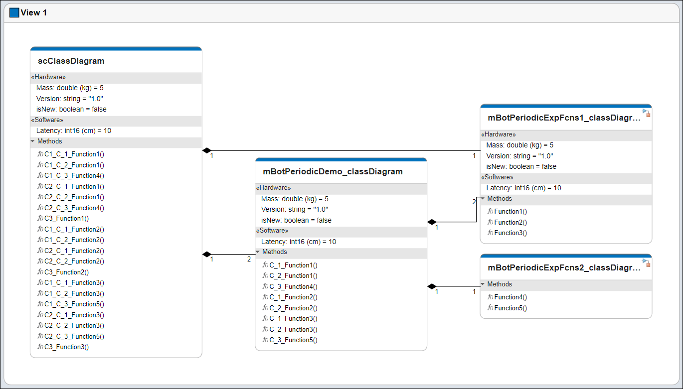
Visualizzare il diagramma dell'architettura software come diagramma di classe in Architecture Views Gallery.
| Termine | Definizione | Applicazione | Maggiori informazioni |
|---|---|---|---|
| Architettura software | Un'architettura software è una specializzazione di un'architettura per sistemi basati su software che include la descrizione delle composizioni software, delle funzioni dei componenti e della loro pianificazione. | Utilizzare le architetture software in System Composer per creare modelli di architettura software composti da componenti software, porte e interfacce. Progettare il modello di architettura software, definire l'ordine di esecuzione delle funzioni dei componenti, simulare il progetto a livello di architettura e generare codice. | |
| Componente software | Un componente software è una specializzazione di un componente per entità software, comprese le sue interfacce. | Implementare un modello di Simulink con funzione di esportazione, un modello basato su rate o un modello JMAAB come componente software, simulare il modello di architettura software e generare codice. | |
| Composizione del software | Una composizione software è un diagramma dei componenti e dei connettori software che rappresenta un'entità software composita, come un modulo o un'applicazione. | Inglobare le funzionalità aggregando o annidando più componenti o composizioni software. | Model Software Architecture of Throttle Position Control System |
| Funzione | Una funzione è un punto di ingresso in cui avviene un trasferimento del controllo del programma, definibile in un componente software. | Utilizzando Functions Editor, è possibile applicare stereotipi alle funzioni nelle architetture software, modificare i tempi di campionamento e specificare il periodo della funzione. | Author and Extend Functions for Software Architectures |
| Elemento funzione | Un elemento funzione descrive gli attributi di una funzione in un'interfaccia client-server. | Modificare il prototipo della funzione su un elemento funzione per modificare il numero e i nomi degli input e degli output della funzione. Modificare le proprietà dell'elemento funzione come si farebbe con le proprietà di altri elementi dell'interfaccia. I tipi di argomenti delle funzioni possono includere tipi integrati e oggetti bus. È possibile specificare gli elementi funzione per supportare:
| systemcomposer.interface.FunctionElement |
| Argomento della funzione | Un argomento della funzione descrive gli attributi di un argomento di input o output in un elemento funzione. | È possibile impostare le proprietà di un argomento di funzione in Interface Editor, proprio come si farebbe con altri tipi di valore: | systemcomposer.interface.FunctionArgument |
| Interfaccia di servizio | Un'interfaccia di servizio definisce l'interfaccia funzionale tra i componenti client e server. Ogni interfaccia di servizio è costituita da uno o più elementi funzione. | Una volta definita un'interfaccia di servizio in Interface Editor, è possibile assegnarla alle porte client e server utilizzando Property Inspector. È inoltre possibile utilizzare Property Inspector per assegnare stereotipi alle interfacce di servizio. | |
| Server | Un server è un componente che definisce e fornisce una funzione. | Un componente server è il punto in cui viene definita la funzione. È possibile implementare il comportamento della funzione in un modello di Simulink con funzione di esportazione. | Service Interfaces Overview |
| Client | Un client è un componente che invia una richiesta al server. | Un componente client è il punto in cui viene chiamata la funzione. L'implementazione del comportamento della chiamata di funzione dipende dalla sincronicità di esecuzione delle funzioni. | Service Interfaces Overview |
| Diagramma di classe | Un diagramma di classe è una rappresentazione grafica di un modello strutturale statico che mostra i tipi di architettura univoci dei componenti software, opzionalmente con metodi e proprietà software. | I diagrammi di classe acquisiscono un'istanza di ciascun modello referenziato e mostrano le relazioni tra di loro. Una vista del diagramma dei componenti può essere rappresentata opzionalmente come un diagramma di classe per un modello di architettura software. | Class Diagram View of Software Architectures |
Vedi anche
Argomenti
- Composizione e analisi dei sistemi utilizzando modelli di architettura
- Organize System Composer Files in Projects
- Simulate Mobile Robot with System Composer Workflow
- Modeling System Architecture of Small UAV