Visualize VTOL Hardware-in-the-Loop (HITL) Simulation over Urban Environment
This example shows how to run and visualize a VTOL aircraft Hardware-in-the-Loop (HITL) simulation in an urban environment using Unreal Engine®. This example leverages the custom actor workflow in UAV Toolbox to visualize aircraft performance in a photorealistic environment.
This example is based on the Visualize VTOL Flight Mission Over Urban Environment example.
Prerequisites
If you have already configured and run the PX4 Hardware-in-the-Loop (HITL) Simulation with VTOL Tilt-Rotor Plant in Simulink, continue with this example. If not, follow the steps in the Prerequisites section of that example before proceeding with this one.
Download and install UAV Toolbox Interface for Unreal Engine Projects. For more information about installing and setting up the UAV Toolbox Interface for Unreal Engine Projects, see Install Support Package for Customizing Scenes.
This example uses a 3D Game Asset Urban Air Mobility Vehicle data set, which contains an FBX file of a VTOL UAV, and is approximately 6 MB in size. Download the VTOLAsset ZIP file from the MathWorks® website, and then unzip the file.
zipFile = matlab.internal.examples.downloadSupportFile("uav","data/VTOLAsset.zip");
filepath = fileparts(zipFile);
dataFolder = fullfile(filepath,"VTOLAsset");
unzip(zipFile,dataFolder)
Getting Started
Load the project and set up the aircraft plant model and parameters for the HITL simulation.
prj = openProject("PX4VTOLHITLSimulinkPlant/VTOLHITL.prj");Alternatively, you can set up the model by using the setupHITLConfiguration, setupPlantControllerParams, and setupHITLController helper functions and assigning the controller and plant models.
% Set HITL configuration parameters
setupHITLConfiguration

% Initialize plant parameters
setupPlantControllerParams

% Initialize controller parameters
setupHITLController

% Controller and plant model
controller_mdl = "HITL_Controller_top.slx";
plant_mdl = "HITL_Plant_top.slx";
Set up City Mission for Unreal Visualization
This section loads the guidance mission which, has flight modes like take-off (in hover), forward transition, fixed-wing. and backward transition.
You can load the sample mission in setupCityMission.m.
setupCityMission
You can customize your flight mission using these modes, based on the format that the Path Manager uses.
Mission Mode 1 — Takeoff UAV
Mission Mode 2 — Fly to a waypoint
Mission Mode 3 — Orbit a point
Mission Mode 4 — Land UAV
Mission Mode 6 — Transition from hover to forward flight or transition to hover from forward flight.
Modes 1 and 4 support only hover mode. Modes 2, 3, and 6 support fixed-wing mode and hover mode.

Note that mode 5 is omitted because it is reserved for RTL mode which is not used in this model.
Deploy controller to Pixhawk target
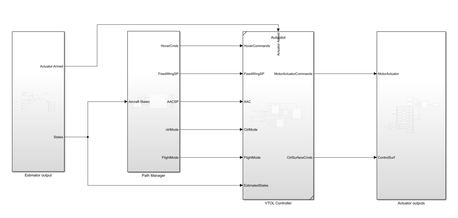
In the HITL controller model, the VTOL Controller subsystem contains a reference flight controller design for a VTOL tilt-rotor UAV model. The Actuator output subsystem parses the controller outputs into uORB messages. The Estimator output subsystem provides the estimated states of the UAV for controller feedback.
Open the HITL_controller_top model.
open_system(controller_mdl)
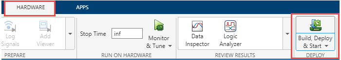
To deploy the model, on the Hardware tab of the Simulink Toolstrip, in the Deploy section, select Build, Deploy & Start. Simulink generates the code for the flight controller and deploys it to the Pixhawk board.
After completing deployment, the model launches QGroundControl.
If you are using Ubuntu, QGroundCcontrol might not launch automatically. To launch QGroundCcontrol, open the terminal and go to the folder where QGroundCcontrol is downloaded and , and then enter this command:
./QGroundControl.AppImageIf you have changed the hardware, or are not using the preconfigured Simulink model, then you must configure your Simulink model as in Configure Simulink Model for Deployment in Hardware-in-the-Loop (HITL) Simulation.
Point Model to Unreal Engine Project
You must use another instance of MATLAB® for the Unreal visualization model operations.
To configure the Unreal Engine and the Simulink model:
Open another instance of MATLAB on your machine.
Load the project, and open the Unreal visualization Simulink model by running these commands in the MATLAB Command Window.
% Open MATLAB project
prj = openProject("VTOLHITL.prj");

% Open Unreal visualization model
open_system("HITL_Unreal_Visualization")

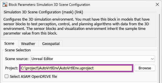
Open the Simulation 3D Scene Configuration block mask and set the Scene source parameter to Unreal Editor. Then, specify the path to the AutoVrtlEnv Unreal Engine project on your system.
If you do not have the AutoVrtlEnv file, you must complete the steps in Install Support Package for Customizing Scenes. The installation and set up process for the UAV Toolbox Interface for Unreal Engine Projects includes setting up the AutoVrtlEnv file.
Import VTOL Vehicle into Unreal Engine Scene
Launch Unreal Editor
In the Photorealistic subsystem, open the Simulation 3D Scene Configuration block mask and select Open Unreal Editor to launch Unreal Editor from MATLAB.

Import VTOL Asset into Unreal Engine Scene
In Unreal Editor, select Add/Import and then New Folder from the context menu. Create a folder called EVTOL in the Content Browser pane, and then open the EVTOL folder.

Select Add/Import, and then Import to Game/EVTOL. Navigate to the folder in which you saved the VTOLAsset file, and select the VTOLAsset file to open the FBX Import Options dialog box.

To select a skeleton mesh:
Open the Skeleton drop-down list, and select View Options.
Select Show Engine Content and Show Plugin Content to add the
UAV_Skeletonmesh option to theSkeletondrop-down list.Set Skeleton to
UAV_Skeleton.

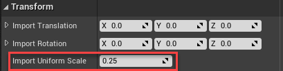
In the Transform section, set the Import Uniform Scale parameter to 0.25 to scale the VTOL asset to a more realistic size.
To finish importing the asset, in Unreal Editor, select Import.
Customize VTOL Asset
In the Content Browser pane of Unreal Editor, select VTOLAsset to open the Asset Details tab.

Select Element 1 of the VTOL skeletal mesh to be the main body of the vehicle, and name it VehicleBody. Verify that Element 1 is the fuselage by selecting Isolate to see which body the element represents, and then save the VTOL asset.

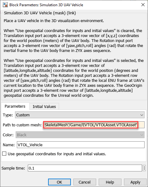
Right-click the VTOLAsset skeletal mesh object in Content Browser pane and select Copy Reference to copy the reference path to this asset.

In the Simulation 3D UAV Vehicle block of the Photorealistic subsystem, set the Type parameter to Custom, and then set the Path to custom mesh parameter to the reference path by pasting the copied reference path.
Visualize VTOL Mission in Urban City Mission
In the Content Browser pane, navigate to the Maps folder and select the USCityBlock asset to load the US City Block scene.

Run Unreal Visualization Simulink Model
In the Simulink Toolstrip of the plant model (HITL_Unreal_Visualization), on the Simulation tab, select Run to simulate the model.

While Simulink is initializing, select Play in Unreal Editor. Zoom out to visualize the UAV flying a mission over the city. You can optionally enable pacing within Simulink to change the simulation speed to real-time, for smoother visualization, by selecting the down-arrow on the Run button, then Simulation Pacing, and selecting Enable pacing to slow down simulation in the Simulation Pacing Options dialog box..
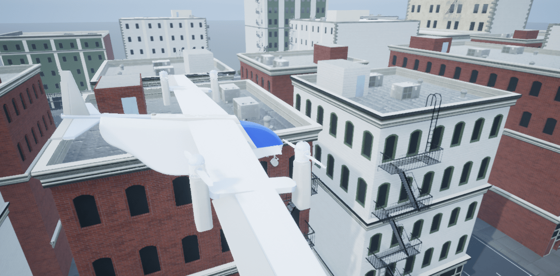
The vehicle coordinates visualized in Unreal are not ground truth, but state-estimated values from the PX4 autopilot.
Run VTOL plant model
To simulate the mission in HITL, open the HITL_Plant_top model. In this model, the MAVLink Bridge Source block reads the MAVLink messages from the Pixhawk board and feeds them to the VTOL Plant subsystem as actuator inputs.
The VTOL Plant subsystem contains the plant model for the VTOL tilt-rotor UAV, which simulates the aerodynamics, propulsion, ground contact, and sensors of a VTOL tilt-rotor UAV. The subsystem outputs sensor, GPS, rotor parameter, and GPS data. The MAVLink Brisge Sink block then receives this data, parses it as MAVLink messages, and sends the messages back to the Pixhawk using the serial connection.

open_system(plant_mdl);
On the Simulink Toolstrip, in the Simulation tab, select Run to start the simulation

Open QGroundControl and select Fly View. Start the mission by arming the vehicle by selecting Arm.

The mission now starts. This mission includes hover mode.

You can also select a web site from the following list:
Americas
- América Latina (Español)
- Canada (English)
- United States (English)
Europe
- Belgium (English)
- Denmark (English)
- Deutschland (Deutsch)
- España (Español)
- Finland (English)
- France (Français)
- Ireland (English)
- Italia (Italiano)
- Luxembourg (English)
- Netherlands (English)
- Norway (English)
- Österreich (Deutsch)
- Portugal (English)
- Sweden (English)
- Switzerland
- United Kingdom (English)