Deploy and Verify YOLO Object Detector Postprocessing on FPGA
R2026bThis example shows how to deploy a you-only-look-once (YOLO) object detector with preprocessing, deep learning (DL) IP, and postprocessing on an FPGA, and verify the design by reading back detection results from the hardware.
The YOLO v2 Vehicle Detector with Live Camera Input on Zynq-Based Hardware example deploys the postprocessing logic to the ARM® processor (PS). This example shows how to deploy the postprocessing logic also onto the FPGA fabric (PL).
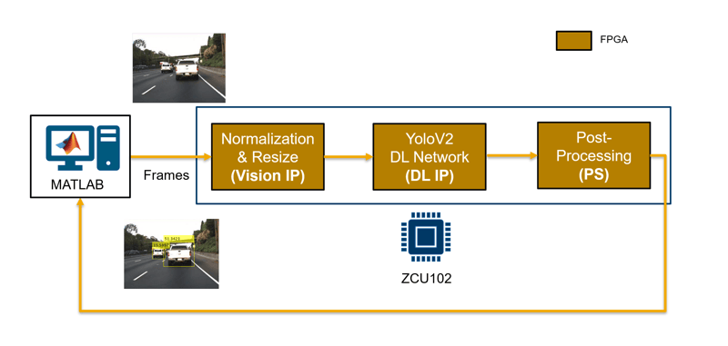
The reference design passes the input image to the preprocessing logic, which resizes and normalizes the frame to 227-by-227 pixels. The DL processor performs YOLOv3 inference, producing two detection heads (14x14x18 and 28x28x18). The postprocessing logic on the FPGA applies the YOLO transform layer, anchor box decoding, and non-maximum suppression (NMS) to produce final bounding boxes. The bounding boxes are read back by MATLAB via AXI4-Lite registers for verification.
The FPGA returns detected bounding boxes as a packed uint64 vector via AXI4-Lite registers, enabling lightweight readback without postprocessing on the processor.
This example uses the Deep Learning with Preprocessing Interface reference design provided in the SoC Blockset™ Support Package for AMD® FPGA and SoC Devices.
Set Up Hardware
This example deploys the algorithm to an AMD® Zynq® UltraScale+(TM) MPSoC ZCU102 Evaluation Kit.
Before running this example, you must install SoC Blockset Support Package for AMD FPGA and SoC Devices and run the guided hardware setup included in the support package installation. The setup tool configures the target board and host machine, confirms that the target starts correctly, and verifies host-target communication.
For more information, see Install Support for AMD FPGA and SoC Devices (SoC Blockset) and Set Up AMD FPGA and SoC Devices (SoC Blockset).
Set up the board's SD card using .
Download Video and Network Files
This example uses PandasetCameraData.mp4 video from the Pandaset dataset as the input video and yolov3SqueezeNetVehicleExample_21aSPKG.mat as the pretrained YOLOv3 SqueezeNet vehicle detection network. Download the .zip file from MathWorks support website and unzip the downloaded file.
PandasetZipFile = matlab.internal.examples.downloadSupportFile('visionhdl','PandasetCameraData.zip');
[outputFolder,~,~] = fileparts(PandasetZipFile);
unzip(PandasetZipFile, outputFolder);
pandasetVideoFile = fullfile(outputFolder,'PandasetCameraData');
addpath(pandasetVideoFile);
Download the pretrained YOLOv3 SqueezeNet vehicle detector.
function detector = downloadPretrainedYOLOv3Detector()
% Download a pretrained YOLOv3 detector.
if ~exist("yolov3SqueezeNetVehicleExample_21aSPKG.mat","file")
    if ~exist("yolov3SqueezeNetVehicleExample_21aSPKG.zip","file")
        disp("Downloading pretrained detector...");
        pretrainedURL = "https://ssd.mathworks.com/supportfiles/vision/data/yolov3SqueezeNetVehicleExample_21aSPKG.zip";
        websave("yolov3SqueezeNetVehicleExample_21aSPKG.zip",pretrainedURL);
    end
    unzip("yolov3SqueezeNetVehicleExample_21aSPKG.zip");
end
pretrained = load("yolov3SqueezeNetVehicleExample_21aSPKG.mat");
detector = pretrained.detector;
end
Load the pretrained detector and configure parameters for the example.
detector = downloadPretrainedYOLOv3Detector();
net = detector.Network;
numFrames = 1;
v = VideoReader("PandasetCameraData.mp4");
inputImages = read(v, numFrames);
Explore the DL System Model
The DL system model DLSystemOnFPGA contains the end-to-end vehicle detection pipeline designed for FPGA deployment. The model's InitFcn callback calls helperSLDLSystemSetup to configure all workspace variables. The model operates in three modes controlled by the setup script: simulation, bitstream generation, and deployment.
open_system('DLSystemOnFPGA');
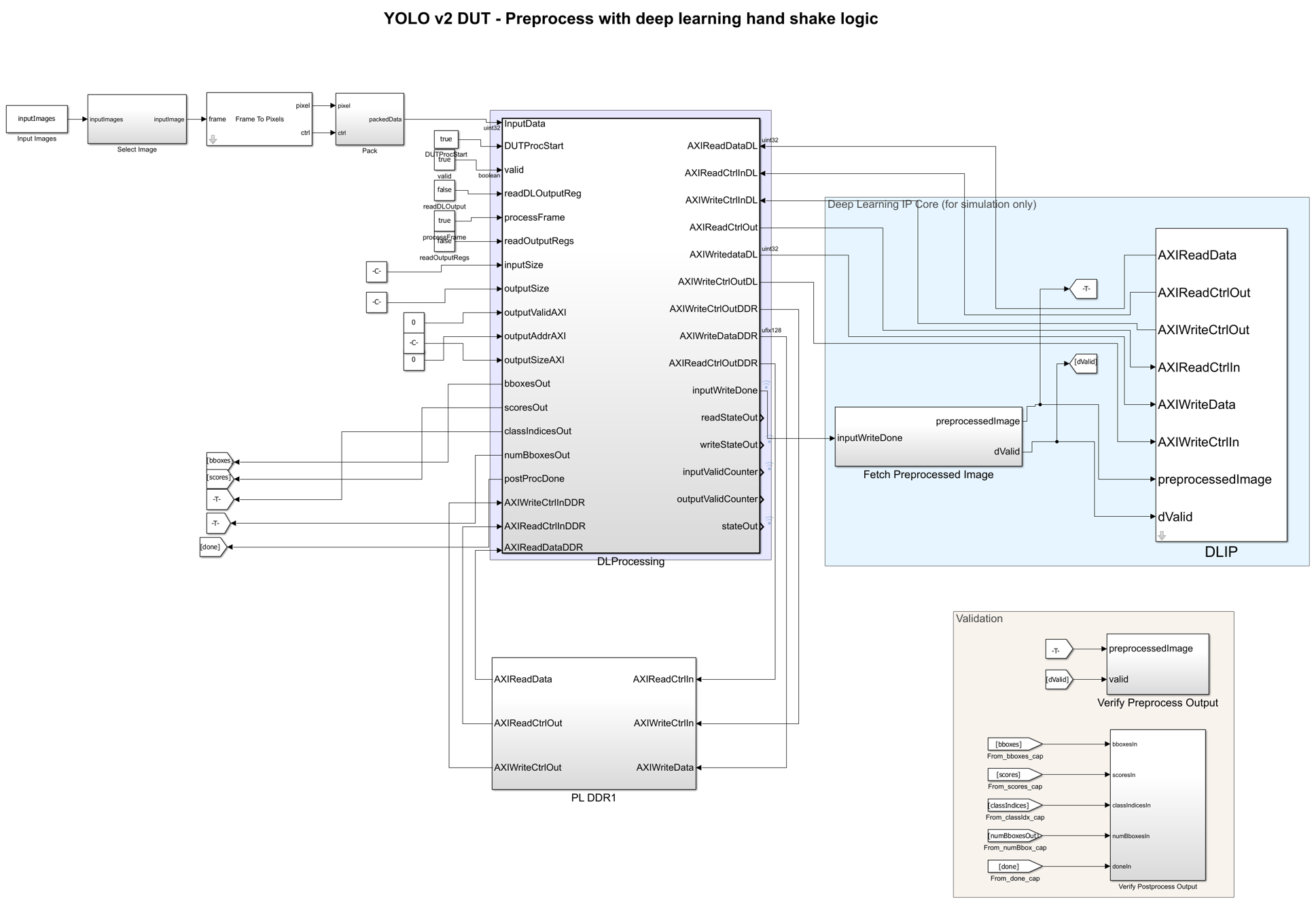
The model contains these parts:
Select Image - Selects the input image from Pandaset.
Frame To Pixels - Converts the input frame into an RGB pixel stream.
DL Processing (DUT) - Preprocesses the input frame, performs DL handshaking, reads DL output, and runs postprocessing to produce bounding boxes. This entire subsystem is targeted to the FPGA.
DLIP - Simulates the DL processor IP core, executing inference and producing output activations in DDR format.
PL DDR - Models the PL DDR memory for simulation.
Validation - Stores preprocessing and postprocessing outputs using To Workspace blocks for verification by the
helperVerifyDLSystemscript.
The DLProcessing subsystem is the design under test (DUT) targeted for FPGA deployment. It contains three main subsystems: Preprocessing, DL Handshaking, and Post processing.
open_system('DLSystemOnFPGA/DLProcessing','force');
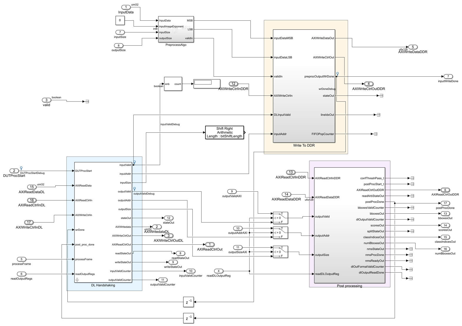
Preprocessing
The Preprocessing subsystem uses the YOLOv2PreprocessAlgorithm referenced model to resize and normalize input frames. This block is reused from the existing Deploy and Verify YOLO v2 Vehicle Detector on FPGA example and is YOLO-version-agnostic (performs resize and normalize only).
open_system('DLSystemOnFPGA/DLProcessing/PreprocessAlgo','force');
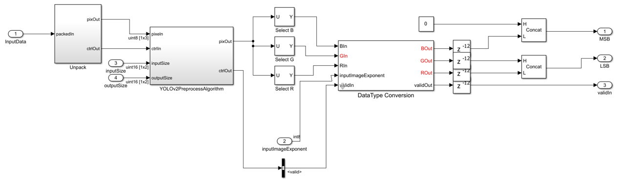
The YOLOv2PreprocessAlgorithm subsystem contains:
Resize - Uses the Image Resizer block to resize the input image to 227-by-227 pixels.
Normalization - Rescales pixel values to [0,1] range using
inputMinandinputMaxfrom the first frame.
The Write To DDR subsystem writes the preprocessed frame to PL DDR using an AXI4 Master interface. The write controller uses a FIFO to buffer the pixel stream and issues burst writes to DDR.
DL Handshaking
The DL Handshaking subsystem manages the communication protocol between the preprocessing, DL processor IP core, and postprocessing logic.
open_system('DLSystemOnFPGA/DLProcessing/DL Handshaking','force');
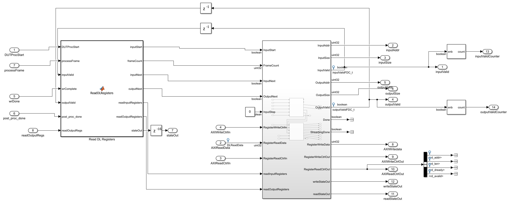
The subsystem implements a master FSM (Read DL Registers) that orchestrates the entire input-DL-output sequence for each frame:
Asserts
InputStartto the DL processor and reads theInputValid,InputAddr, andInputSizeregisters to determine where to write the preprocessed frame.Waits for the preprocessing write to DDR to complete.
Pulses
InputNextto signal the DL processor that new input data is available.Waits for DL inference to complete and reads the
OutputValid,OutputAddr, andOutputSizeregisters to determine where to read the DL output.Waits for postprocessing to complete and pulses
OutputNextto signal that the output has been consumed.
The master FSM interacts with the Read DLP Registers and Write DLP Registers blocks, which handle the low-level AXI register read/write protocol with the DL processor IP core. For more information on the register-mode handshaking protocol, see Interface with the Deep Learning Processor IP Core (Deep Learning HDL Toolbox).
The model includes debug signals (state outputs, counters, and valid flags) that you can use with FPGA Data Capture for on-chip debugging during hardware verification.
Postprocessing
The Post processing subsystem reads the DL output from DDR and performs the complete YOLO postprocessing pipeline on the FPGA.
open_system('DLSystemOnFPGA/DLProcessing/Post processing','force');
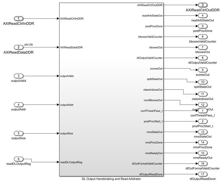
The subsystem contains:
Deep Learning HDL Output Format - A library block shipped by Deep Learning HDL Toolbox™ that converts the DL processor external memory format data to streaming data and valid signals. For more information, see Deep Learning HDL Output Format (Deep Learning HDL Toolbox) block reference page.
Read From DDR - Reads DL output from PL DDR via AXI4 Master using the address and size from the output handshaking registers.
YOLO Postprocessing - A Vision HDL Toolbox™ block that performs the YOLO transform layer (sigmoid, exp), anchor box decoding, and streaming non-maximum suppression (NMS). For more information, see YOLO Postprocessing block reference page.
The postprocessing block produces bounding boxes scaled to the original input dimensions. The output bounding boxes are packed as a uint64 vector (one uint64 per detection: [x(16), y(16), w(16), h(16)] bits) and mapped to AXI4-Lite registers:
bboxesOut-uint64[16x1] packed bounding boxesnumBboxesOut- Number of valid detectionsscoresOut- Confidence scores of detectionsclassIndicesOut- Class indices of detections
DL Inference Simulation
The DLIP subsystem simulates the DL processor IP core. It calls the fetchAndFormatDLOutputs function to run inference on the preprocessed image and format all network outputs into a single DDR vector. This function pads each activation output to the data parallel transfer number and converts it to the External Memory format required by the DL processor IP. The formatted outputs are concatenated into a 1-by-|paddedOutputSize| vector that matches the layout the hardware DL processor writes to DDR.
Configure the Model
The helperDLSetup script is the single entry point for running this example. It defines the detector, input images in one place and passes them to helperSLDLSystemSetup for each workflow. To use a different detector or dataset, modify only the top section of helperDLSetup. The script contains three sections - Simulation, Bitstream Generation, and Deployment - that you run independently.
The helperSLDLSystemSetup function accepts these arguments:
mode-"simulation","bitstreamGen", or"deployment"detector- YOLO object detector (e.g.,yolov3ObjectDetector)inputImages- H-by-W-by-3-by-N input image stackhPC-dlhdl.ProcessorConfigobject defining the DL processor
The function builds a params struct with network, anchors, and scale parameters, assigns all fields to the base workspace, and then calls the helperSLDLSystemParamSetup script which derives all model parameters. In simulation mode, input images are downscaled for faster execution.
The ConvThreadNumber property of the DL processor configuration must be at least 9 for this example. The minimum value of 9 ensures that the dataTransferNumber (computed as power(2, nextpow2(sqrt(CT)))) is at least 4, which matches the DDR format expected by the postprocessing logic. A ConvThreadNumber of 16 is recommended for optimal throughput on the ZCU102.
The example is configured to simulate one frame due to the large simulation time required for multi-frame execution. To simulate additional frames, increase the numFrames variable in the helperDLSetup script before running the simulation section.
Simulate the DL System
Configure the model for simulation by calling the helperSLDLSystemSetup function with mode set to "simulation".
helperSLDLSystemSetup("simulation", detector, inputImages, hPC);
When you compile the model for the first time, the diagram takes a few minutes to update. Update the model before running the simulation.
set_param("DLSystemOnFPGA", SimulationCommand="update");
out = sim("DLSystemOnFPGA");
Verify Simulation Results
The helperVerifyDLSystem script verifies the simulation outputs stored by the Validation subsystem. It performs two comparisons:
Preprocess verification - Compares the preprocessed image from the DUT against a MATLAB reference obtained by applying
imresizeandrescaleto the input image. Displays both images with an absolute difference map.Postprocess verification - Unpacks the
uint64bounding boxes from simulation, computes reference detections by callingpredicton the network followed byprocessYOLOv3Output, and overlays both sets of bounding boxes (reference and simulation) on the input image.
helperVerifyDLSystem;
The script displays comparison figures showing the preprocessed image difference and the bounding boxes from simulation matched against the reference detections.
Configure Deep Learning Processor and Generate IP Core
The DL processor IP core reads the preprocessed input from the PL DDR memory, performs vehicle detection using the YOLOv3 network, and writes the output back into memory. To generate a DL processor IP core that has the required interfaces, create a deep learning processor configuration by using the dlhdl.ProcessorConfig (Deep Learning HDL Toolbox)InputRunTimeControl and OutputRunTimeControl parameters to indicate the type of interface between the input and output of the DL processor. To learn about these parameters, see Interface with the Deep Learning Processor IP Core (Deep Learning HDL Toolbox). In this example, the DL processor uses the register mode for input and output run-time control.
hPC = dlhdl.ProcessorConfig;
hPC.InputRunTimeControl = "register";
hPC.OutputRunTimeControl = "register";
Set the TargetPlatform property of the processor configuration object to Generic Deep Learning Processor. This option generates a custom generic DL processor IP core.
hPC.TargetPlatform = 'Generic Deep Learning Processor';
You can configure the DL processor manually or use the optimizeConfigurationForNetwork (Deep Learning HDL Toolbox) function to automatically set memory sizes and module properties for the network. In this example, use optimizeConfigurationForNetwork first and then manually set ConvThreadNumber to 16 to balance throughput and resource utilization for this network on the ZCU102.
vehicleDetector = load("yolov3SqueezeNetVehicleExample_21aSPKG.mat");
net = vehicleDetector.detector.Network;
optimizeConfigurationForNetwork(hPC, net);
This example uses the AMD ZCU102 board to deploy the DL processor. Use the hdlsetuptoolpath function to add the AMD Vivado synthesis tool path to the system path. The vivadopath variable must contain the path to your Vivado installation. For the latest supported tool versions, see HDL Language Support and Supported Third-Party Tools and Hardware (HDL Coder).
hdlsetuptoolpath('ToolName','Xilinx Vivado','ToolPath', vivadopath);
To generate the DL IP core, call the dlhdl.buildProcessor function with the hPC object. It takes some time to generate the IP core.
dlhdl.buildProcessor(hPC);
The generated DL IP core contains a standard set of registers for DL Handshaking. The function also generates the IP core report, testbench_ip_core_report.html, in the same folder as the DL IP core.
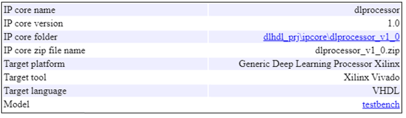
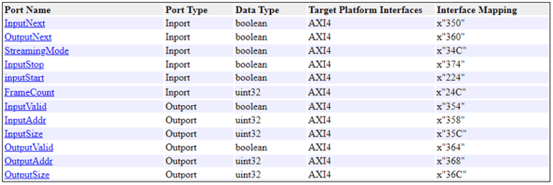
The IP core name and IP core folder are required in a subsequent step in the Set Target Reference Design task of the IP core generation workflow for the rest of the FPGA-targeted design. The IP core report also has the address map of the input and output handshaking registers of the DL processor. The registers InputValid, InputAddr, and InputSize contain the handshaking signals required to write the preprocessed frame into DDR memory. The helperSLDLSystemParamSetup script sets up these register addresses. For more details on interface signals, see the Design Processing Mode Interface Signals section of Interface with the Deep Learning Processor IP Core (Deep Learning HDL Toolbox).
Generate Bitstream
Configure the model for bitstream generation by calling the helperSLDLSystemSetup function with mode set to "bitstreamGen". This mode uses full-resolution images and configures the model for HDL code and bitstream generation.
helperSLDLSystemSetup("bitstreamGen", detector, inputImages, hPC);
Start the targeting workflow by right clicking the DLProcessing subsystem and selecting HDL Code > HDL Workflow Advisor.
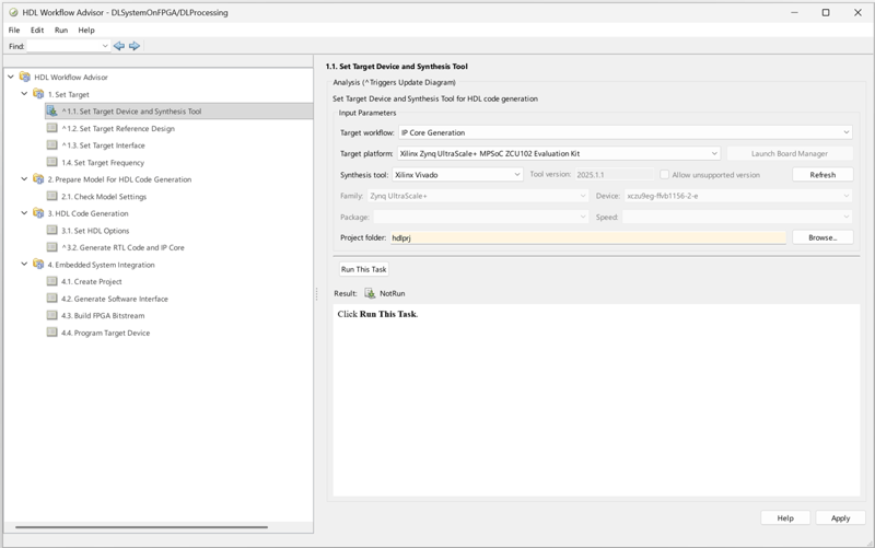
In step 1.1, set Target workflow to IP Core Generation and Target platform to Xilinx Zynq Ultrascale+ MPSoC ZCU102 Evaluation Kit.
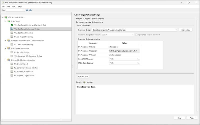
In step 1.2, set Reference design to Deep Learning with Preprocessing Interface. Specify the name and location of the generated DL processor IP core from the IP core report. Specify the vendor name from the component.xml file of the DL processor IP core.
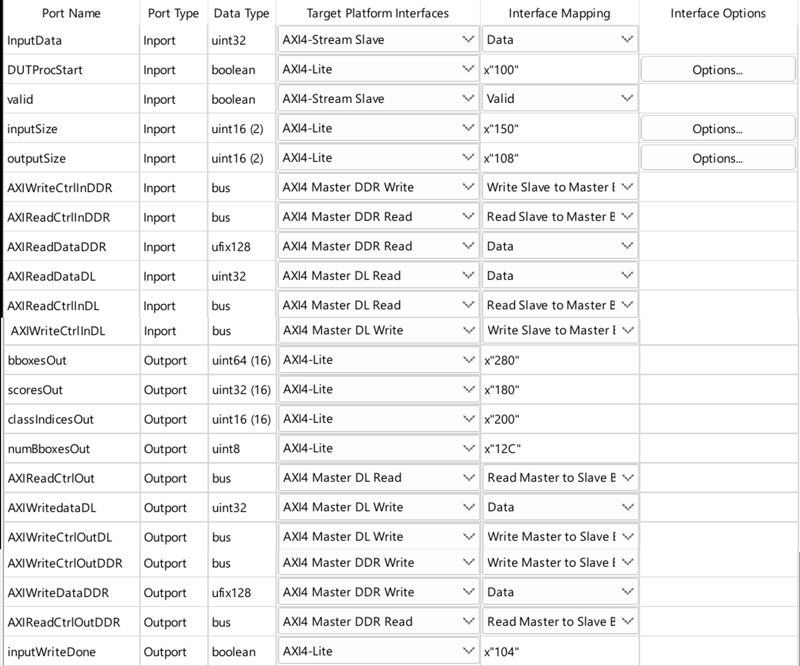
In step 1.3, map the target platform interfaces to the input and output ports of the DUT.
Map the pixel input stream to the AXI4-Stream Slave interface.
Map
DUTProcStart,bboxesOut,numBboxesOut,scoresOut, and other control registers to AXI4-Lite registers. Choosing the AXI4-Lite interface directs HDL Coder™ to generate memory-mapped registers in the FPGA fabric.Map the DDR read and write ports to AXI4 Master DDR interfaces for data transfer between the DUT and PL DDR.
Map the DL handshaking ports to AXI4 Master DL interfaces for register-mode communication with the DL processor IP core.
Step 2 prepares the design for HDL code generation by running design checks.
Step 3 generates HDL code for the IP core.
Step 4.1 integrates the newly generated IP core into the reference design.
In step 4.2, the advisor generates a targeted hardware interface model. Clear Generate Simulink software interface model and Generate host interface script since this example uses a custom deployment verification script.
Step 4.3 generates the bitstream. The bit file is named block_design_wrapper.bit and located at hdl_prj\vivado_ip_prj\vivado_prj.runs\impl_1.
Compile and Deploy Deep Learning Network
Use the programDLSystemOnFPGA script to deploy the generated bitstream and load the network weights onto the device. The following steps show the operations performed by this script.
First, update the bitstream build information. Create a dlhdl.Bitstream object from the generic MAT file generated during IP core generation. Then load the board and reference design plugin information.
bitstreamName = 'block_design_wrapper';
hBitstream = dlhdl.Bitstream('dlprocessor.mat');
hB = DLZCU102.plugin_board;
hRD = DLZCU102.matlab_libiio_3axi4_master_2019_1.plugin_rd;
loadInfoFromPlugin(hBitstream, 'BoardPlugin', hB, 'RefDesignPlugin', hRD);
saveBitstreamInfoFile(hBitstream);
copyfile('dlprocessor.mat', [bitstreamName,'.mat'], 'f');
Create a target object to connect your target device to the host computer. Use the installed AMD Vivado Design Suite over an Ethernet connection to program the device.
hTarget = dlhdl.Target('Xilinx','Interface','Ethernet','IpAddr','192.168.1.101');
Load the pretrained YOLOv3 SqueezeNet vehicle detection network.
vehicleDetector = load("yolov3SqueezeNetVehicleExample_21aSPKG.mat");
detector = vehicleDetector.detector;
net = detector.Network;
Create a deep learning HDL workflow object using the dlhdl.Workflow class. The bitstreamName variable contains the name of the generated bitstream.
hW = dlhdl.Workflow('Network', net, 'Bitstream', [bitstreamName,'.bit'], 'Target', hTarget);
Compile the network using the dlhdl.Workflow object. The InputFrameNumberLimit parameter specifies the number of frame buffers in DDR.
frameBufferCount = 3;
compile(hW, 'InputFrameNumberLimit', frameBufferCount);
Create a Xilinx processor hardware object and connect to the SoC board.
hSOC = xilinxsoc('192.168.1.101', 'root', 'root');
Program the FPGA with the generated bitstream.
programFPGA(hSOC, [bitstreamName,'.bit'], 'devicetree_vision_dlhdl.dtb');
Run the deploy function to download the network weights and biases onto the board. Set ProgramBitStream to false because the bitstream is already programmed.
deploy(hW, 'ProgramBitStream', false);
Clear the workflow and hardware target objects.
clear hW;
clear hTarget;
Verify Detection Results on FPGA
After programming the FPGA and deploying the network, verify the design by sending input frames from MATLAB and reading back the detection results. The inputImages variable must contain full-resolution (unscaled) frames for deployment. If you previously ran the simulation section with scaled images, regenerate inputImages at full resolution with the desired number of frames before running this section.
Configure workspace variables for deployment mode.
helperSLDLSystemSetup("deployment", detector, inputImages, hPC);
Run the VerifyYOLOv3DetectorOnFPGA script to perform end-to-end verification. This script connects to the FPGA, sets up the DL IP and preprocessing interfaces, configures streaming mode, sends each input frame via AXI4-Stream, and reads back detection results from AXI4-Lite registers.
VerifyYOLOv3DetectorOnFPGA;
The script performs these operations:
Connects to the FPGA using the
hSOCprocessor hardware object.Sets up DL processor interfaces using
setupDLProcessorInterfacesand DUT interfaces usingsetupDUTInterfaces.Writes PL DDR4 base address registers (
0x80000000) for the AXI4 Master read and write interfaces.Configures the DL processor for streaming mode and asserts
DUTProcStartto start the pipeline.For each input frame, packs the image for AXI4-Stream transfer and sends it to the preprocessing IP.
Reads detection results:
numBboxesOut,bboxesOut(uint64packed),scoresOut, andclassIndicesOutfrom AXI4-Lite registers.Unpacks the
uint64bounding boxes into [x, y, w, h] coordinates and overlays each detection with its class name and confidence score.
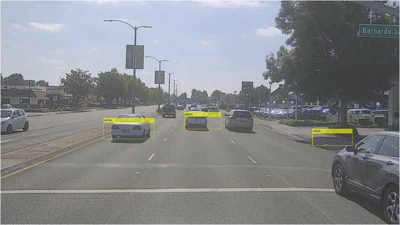
The bounding boxes from the FPGA match the simulation results, confirming that the end-to-end pipeline (preprocessing, DL inference, and postprocessing) operates correctly on the hardware.
See Also
YOLO Postprocessing | Deep Learning HDL Output Format (Deep Learning HDL Toolbox) | Deep Learning HDL Handshake Interface (Deep Learning HDL Toolbox)

