NR HDL SIB1 Recovery
This example shows how to design a 5G NR system information block type 1 (SIB1) recovery model optimized for HDL code generation and hardware implementation.
Introduction
SIB1 recovery requires cell search, master information block (MIB) decoding, recovery of the SIB1 grid (the area of the resource grid containing CORESET0 and SIB1), and decoding of the CORESET0 PDCCH and SIB1 PDSCH from the SIB1 grid. The process of Cell Search and MIB recovery are described in the NR HDL Cell Search and NR HDL MIB Recovery examples respectively. The additional models used to implement SIB1 grid recovery, CORESET0 decoding, and SIB1 decoding are described in the Hardware Accelerators for NR SIB1 Recovery example. This example focuses on the SIB1 Recovery Simulink model and uses the MATLAB reference to generate test input and verify the behavior of the model.

The Simulink® models described in this example are fixed-point HDL optimized implementations of SIB1 recovery for 5G NR frequency range 1 (FR1). This example is one of a related set, for more information see NR HDL Reference Applications Overview.
File Structure
This example uses these files.
Simulink models
nrhdlSIB1Recovery.slx: This Simulink model combines the processing of the SSB detector, SSB decoder, SIB1 demodulator, CORESET0 decoder, and SIB1 decoder into an integrated model illustrating the complete SIB1 grid recovery process. This model references thenrhdlDDCFR1Core,nrhdlSSBDetectionFR1Core,nrhdlSSBDecodingCore,nrhdlPolarDecodingChainCore,nrhdlSIB1DemodulationFR1Core,nrhdlCORESET0DecodingCore, andnrhdlLDPCDecodingChainCoremodels.nrhdlDDCFR1Core.slx: This model implements a DDC to create sample streams for SIB1 and SSBs.nrhdlSSBDetectionFR1Core.slx: This model implements the SSB detection algorithm.nrhdlSSBDecodingCore.slx: This model implements the SSB decoding algorithm.nrhdlPolarDecodingChainCore.slx: This model implements the common polar decoding chain.nrhdlSIB1DemodulationFR1Core.slx: This model implements the SIB1 demodulation algorithm.nrhdlCORESET0DecodingCore.slx: This model implements the CORESET0 decoding algorithm.nrhdlLDPCDecodingChainCore.slx: This model implements the SIB1 LDPC decoding algorithm.
Simulink data dictionary
nrhdlReceiverData.sldd: This Simulink data dictionary contains bus objects that define the buses contained in the example models.
MATLAB code
runNRSIB1RecoveryModel.m: This script uses the MATLAB reference to perform the search mode of the SSB detection algorithm, then runs thenrhdlSIB1RecoverySimulink model to demodulate and decode the SSB, and then demodulate the SIB1 grid. The script performs CORESET0 and SIB1 decoding using either MATLAB code designed for embedded software or the hardware accelerators in thenrhdlSIB1Recoverymodel.nrhdlexamples: Namespace containing the MATLAB reference code and utility functions for verifying the implementation models.
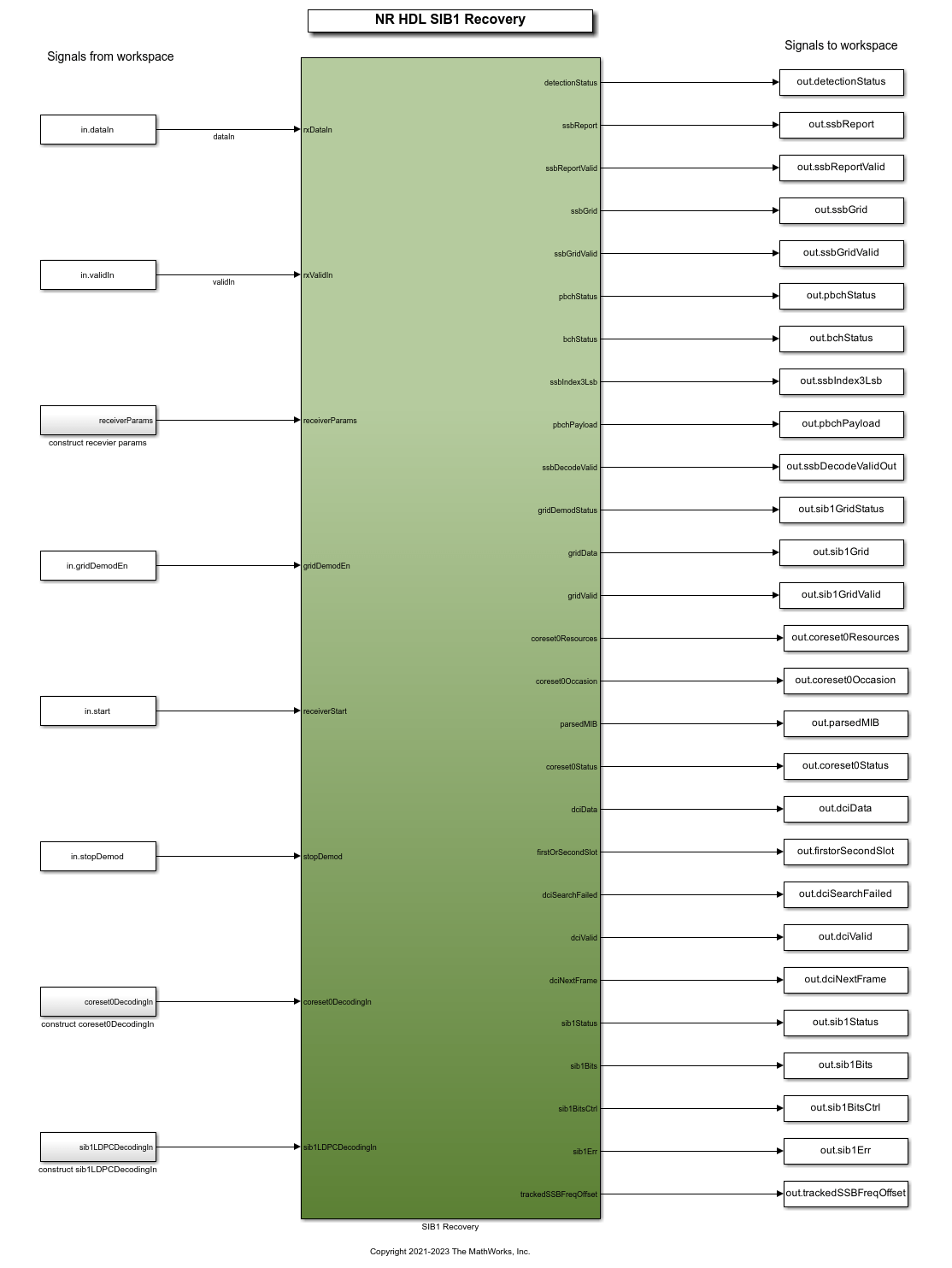
NR HDL SIB1 Recovery
This figure shows the nrhdlSIB1Recovery model. The top level of the model reads the signals from the MATLAB base workspace, passes them to the SIB1 Recovery subsystem, and writes the outputs back to the workspace. The model implements SIB1 recovery through a set of hardware accelerators which are controlled from software when deployed to an SoC device. The design operates on a baseband 5G waveform and performs initial access up to the decoding of the SIB1.
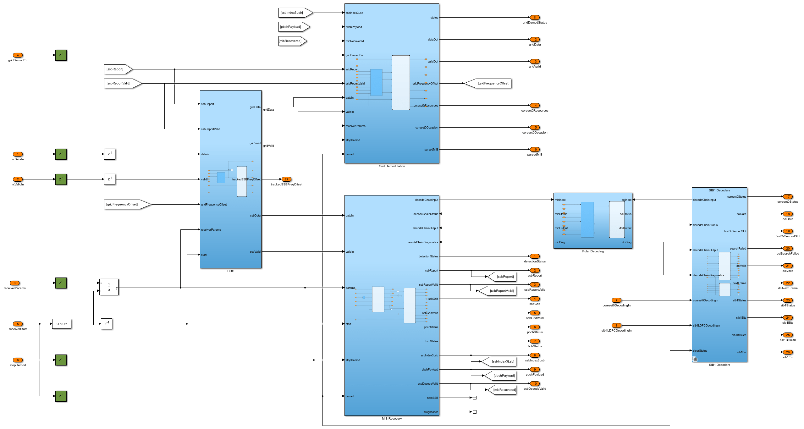
SIB1 Recovery Subsystem
The SIB1 Recovery subsystem references models and combines them to create the full SIB1 recovery design. The appendix of this example contains a full description of the subsystem interface. The software control loop co-ordinates the process to setup inputs and monitor the outputs for each stage.
More information on each model referenced by the SIB1 Recovery subsystem can be found in these examples.
The NR HDL Cell Search example details:
nrhdlDDCFR1CorenrhdlSSBDetectionFR1Core
The NR HDL MIB Recovery example details:
nrhdlSSBDecodingCorenrhdlPolarDecodingChainCore
The Hardware Accelerators for NR SIB1 Recovery example details:
nrhdlSIB1DemodulationFR1CorenrhdlCORESET0DecodingCorenrhdlLDPCDecodingChainCore
SIB1 Recovery Operations
The design operates in one of four modes - search, demodulation, CORESET0 decode, and SIB1 decode. A full SIB1 recovery consists of one or more searches followed by a demodulation operation, a CORESET0 decode operation, and finally a SIB1 decode operation. The SIB1 recovery operations extend the MIB recovery operations in the NR HDL MIB Recovery example.
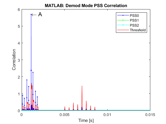
1. Search Mode
The search mode behavior is unchanged from the cell search and MIB recovery designs. The SSB detector searches for SSBs at the specified subcarrier spacing and frequency offset by correlating against each PSS sequence. The operation outputs a list of the detected SSBs, defined by a timing offset and PSS sequence ID.
2. Demodulation Mode
The demodulation mode operation is extended from the MIB recovery design by including the SIB1 grid demodulator. The decoded MIB from the SSB decoder is used to locate and demodulate the SIB1 grid. In single demodulation mode, one SIB1 grid is demodulated after the SSB grid is decoded. In repeat demodulation mode, a SIB1 grid is demodulated after each SSB is decoded.
3. CORESET0 Decode Mode
This operation decodes CORESET0 to recover the SIB1 DCI by performing a blind search across each search space and monitored slot. The algorithm operates on data extracted from the SIB1 grid recovered in the previous step. The process of extracting the input data for this operation from the SIB1 grid is performed in software.
4. SIB1 Decode Mode
This operation performs LDPC decoding, code block desegmentation, and CRC decoding to recover the final SIB1 payload. The input data is extracted from the SIB1 grid in software using the DCI from the CORESET0 decode operation to select the allocated symbols.
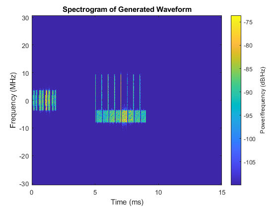
SIB1 Recovery Simulation Setup
The block diagram shows the simulation setup implemented by this example. The orange blocks highlight the comparison points between the MATLAB reference and the Simulink HDL implementation. The runNRSIB1RecoveryModel script runs the simulation, the MATLAB code represents the software control algorithm and the Simulink simulations perform the FPGA processing. 5G Toolbox™ functions are used to generate a test waveform. MATLAB reference code is used to perform the SSB search stage in place of running the Simulink simulation. The MATLAB reference provides equivalent results and improves simulation speed because it runs faster than the Simulink simulation. The results of the MATLAB SSB search is passed to both MATLAB and Simulink implementations of SIB1 recovery, and the output grids are directly compared. The Simulink SIB1 grid is decoded by one of two methods. The default option uses the nrhdlSIB1Recovery model to simulate the hardware accelerators for CORESET0 and SIB1 decoding. The second option uses a MATLAB only decode algorithm. When the design is deployed to an SoC the first option reduces the computations performed by the embedded processor by offloading the calculations to the FPGA. The second option performs all processing in software allowing for the algorithm to be easily modified and updated without rebuilding the FPGA bitstream.

The Test bench options section of the runNRSIB1RecoveryModel script includes these variables to configure the simulation:
simulationCase: specifies the configuration of the generated waveform. The table shows the set of simulation cases.
    Simulation Case    SSB Pattern    Subcarrier Spacing Common    PDCCH Config SIB1    SNR dB    Strongest SSB index    Lmax
    _______________    ___________    _________________________    _________________    ______    ___________________    ____

      "SimCase 1"       "Case C"                 30                       164             50               4              8
      "SimCase 2"       "Case B"                 15                       100              6               3              4
      "SimCase 3"       "Case A"                 30                         4             20               2              8
      "SimCase 4"       "Case A"                 15                        84              7               0              4
numSubFrames: specifies the number of 1 ms subframes generated as input stimulus.
searchInSimulink: specifies whether to run the search step in MATLAB (false) or Simulink (true). Performing the search in MATLAB reduces the simulation time and is sufficient for verifying the demodulation and decoding operations. Performing the search in Simulink allows you to verify the
nrhdlSIB1Recoverymodel in search mode.repeatDemodEn: specifies single or repeat demodulation mode.
useHardwareAccelerators: specifies whether to simulate the hardware accelerator behaviour for decoding CORESET0 and SIB1, or to use the software only MATLAB code.
SIB1 Recovery Simulation
Use the runNRSIB1RecoveryModel script to run a SIB1 recovery simulation. The script displays its progress at the MATLAB command prompt, and produces plots of inputs and outputs for analysis.
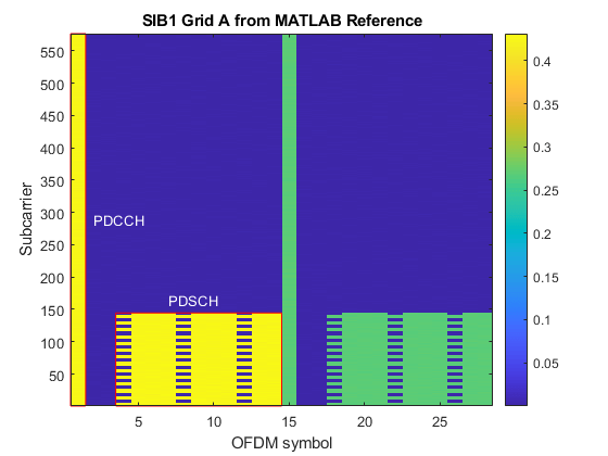
This example shows the results of running "SimCase 1". The resource grids produced by MATLAB and Simulink are displayed along with their relative mean squared error (MSE). This comparison verifies that the Simulink implementation closely matches the MATLAB reference. The grid plots are labeled to highlight the decoded PDCCH and PDSCH. The final stage of the script decodes CORESET0, displays the DCIs, and decodes SIB1. The result of the SIB1 decode is displayed, and the SIB1 bits from MATLAB and Simulink are compared to verify that they match.
runNRSIB1RecoveryModel;
Generating test waveform.
Selected Simulation case:

    Simulation Case    SSB Pattern    Subcarrier Spacing Common    PDCCH Config SIB1    SNR dB    Strongest SSB index    Lmax
    _______________    ___________    _________________________    _________________    ______    ___________________    ____

      "SimCase 1"       "Case C"                 30                       164             50               4              8

Searching for SSBs using the MATLAB reference.
    NCellID2    timingOffset    pssCorrelation    pssEnergy    frequencyOffset
    ________    ____________    ______________    _________    _______________

       0               4416         0.8229         0.90807          5057
       0              17568        0.65622         0.72268          4992
       0              35136         1.6519          1.8197          5019
       0              48288         1.2985          1.4337          5041
       0              65856         5.2009          5.7299          4938
       0              79008         2.0651          2.2745          4996
       0              96576         1.0396          1.1439          5005
       0         1.0973e+05        0.73366         0.80827          4993

Recover the SIB1 grid using MATLAB reference.
Recovering the SIB1 grid using the MATLAB reference.
Recover the SIB1 grid using Simulink model.
Running nrhdlSIB1Recovery.slx
### Searching for referenced models in model 'nrhdlSIB1Recovery'.
### Total of 7 models to build.
### Starting serial model build.
### Successfully updated the model reference simulation target for: nrhdlCORESET0DecodingCore
### Successfully updated the model reference simulation target for: nrhdlDDCFR1Core
### Successfully updated the model reference simulation target for: nrhdlLDPCDecodingChainCore
### Successfully updated the model reference simulation target for: nrhdlPolarDecodingChainCore
### Successfully updated the model reference simulation target for: nrhdlSIB1DemodulationFR1Core
### Successfully updated the model reference simulation target for: nrhdlSSBDecodingCore
### Successfully updated the model reference simulation target for: nrhdlSSBDetectionFR1Core

Build Summary

Model reference simulation targets:

Model                         Build Reason                       Status                        Build Duration
=============================================================================================================
nrhdlCORESET0DecodingCore     Code replacement library changed.  Code generated and compiled.  0h 0m 15.581s
nrhdlDDCFR1Core               Code replacement library changed.  Code generated and compiled.  0h 1m 1.8443s
nrhdlLDPCDecodingChainCore    Code replacement library changed.  Code generated and compiled.  0h 1m 34.064s
nrhdlPolarDecodingChainCore   Code replacement library changed.  Code generated and compiled.  0h 1m 4.7555s
nrhdlSIB1DemodulationFR1Core  Code replacement library changed.  Code generated and compiled.  0h 1m 3.613s
nrhdlSSBDecodingCore          Code replacement library changed.  Code generated and compiled.  0h 0m 26.451s
nrhdlSSBDetectionFR1Core      Code replacement library changed.  Code generated and compiled.  0h 2m 28.804s

7 of 7 models built (0 models already up to date)
Build duration: 0h 8m 10.882s
..........

------------- Displaying Results for SIB1 grid A -------------

SSB demodulated at: 1.0719 ms

MATLAB and Simulink grids relative MSE : -61.236 dB

Extracting CORESET0 candidates from the SIB1 grid.
Decoding CORESET0 candidates using MATLAB reference.
Decoding CORESET0 candidates using Simulink.
Running nrhdlSIB1Recovery.slx
### Searching for referenced models in model 'nrhdlSIB1Recovery'.
### Total of 7 models to build.
### Model reference simulation target for nrhdlCORESET0DecodingCore is up to date.
### Model reference simulation target for nrhdlDDCFR1Core is up to date.
### Model reference simulation target for nrhdlLDPCDecodingChainCore is up to date.
### Model reference simulation target for nrhdlPolarDecodingChainCore is up to date.
### Model reference simulation target for nrhdlSIB1DemodulationFR1Core is up to date.
### Model reference simulation target for nrhdlSSBDecodingCore is up to date.
### Model reference simulation target for nrhdlSSBDetectionFR1Core is up to date.

Build Summary

0 of 7 models built (7 models already up to date)
Build duration: 0h 0m 0.95195s
..........

DCI from MATLAB:
                     RIV: 528
                TDDIndex: 0
    VRBToPRBInterleaving: 0
               ModCoding: 0
                      RV: 0
             SIIndicator: 0
                Reserved: 0

DCI from Simulink:
                     RIV: 528
                TDDIndex: 0
    VRBToPRBInterleaving: 0
               ModCoding: 0
                      RV: 0
             SIIndicator: 0
                Reserved: 0

DCI successfully decoded from Simulink grid with hardware acceleration

Extracting LDPC codeword from the SIB1 grid.
Decoding SIB1 using MATLAB reference.
Decoding SIB1 using Simulink.
Running nrhdlSIB1Recovery.slx
### Searching for referenced models in model 'nrhdlSIB1Recovery'.
### Total of 7 models to build.
### Model reference simulation target for nrhdlCORESET0DecodingCore is up to date.
### Model reference simulation target for nrhdlDDCFR1Core is up to date.
### Model reference simulation target for nrhdlLDPCDecodingChainCore is up to date.
### Model reference simulation target for nrhdlPolarDecodingChainCore is up to date.
### Model reference simulation target for nrhdlSIB1DemodulationFR1Core is up to date.
### Model reference simulation target for nrhdlSSBDecodingCore is up to date.
### Model reference simulation target for nrhdlSSBDetectionFR1Core is up to date.

Build Summary

0 of 7 models built (7 models already up to date)
Build duration: 0h 0m 0.5075s
..........

SIB1 successfully decoded from Simulink grid with hardware acceleration
SIB1 bits from MATLAB and Simulink match

Further Exploration
This section shows how to run a simulation in repeat demodulation mode by modifying the options described in the Simulation Setup section.
Increase the length of the generated waveform to contain a second SSB and SIB1 transmission. Generating a waveform with 35 subframes provides enough input data to perform two SIB1 demods in repeat mode. Increase the value further to perform more demodulations.
numSubFrames = 35;
Enable the repeat demodulation mode to perform multiple demodulations.
repeatDemodEn = 1;
Run the runNRSIB1RecoveryModel script to perform the simulation.
With this input configuration the receiver demodulates two SIB1 grids in demodulation mode, and decodes SIB1 from both grids. The PSS correlation plot shows the peaks of both SSB demodulation occasions, labeled A and B. The SIB1 Grid plots show the SIB1 grids from MATLAB and Simulink for each demodulation. Results are displayed for both demodulations in the Command Window.
HDL Code Generation and Implementation Results
To generate the HDL code for this example, you must have the HDL Coder™ product. Use the makehdl and makehdltb commands to generate HDL code and an HDL test bench for nrhdlSIB1Recovery/SIB1 Recovery subsystems. The resulting HDL code was synthesized for a Xilinx® Zynq® UltraScale+ RFSoC ZCU111 evaluation board. The table shows the post place and route resource utilization results. The design meets timing with a clock frequency of 245.76 MHz.
Resource utilization for nrhdlSIB1dRecovery model:
       Resource        Usage
    _______________    ______

    Slice Registers    119049
    Slice LUTs          82660
    RAMB18                327
    RAMB36                 35
    DSP48                 283
To deploy the nrhdlSIB1Recovery model to a hardware platform and recover SIB1 from off the air signals, see the Deploy NR HDL Reference Applications on FPGAs and SoCs example.
Appendix
SIB1 Recovery Interface
Inputs
dataIn: 14-bit signed complex-valued signal, sampled at 61.44 Msps.
validIn: 1-bit control signal to validate dataIn.
receiverParams: Bus signal containing parameter values used for SSB search, demodulation, and SIB1 grid recovery.
gridDemodEn: 1-bit control signal to enable grid demodulation.
receiverStart: 1-bit control signal used to start a search or demodulation operation.
stopDemod: 1-bit control signal to stop the repeat demodulation mode operation before the timeout count is reached.
coreset0DecodingIn: Bus signal containing the input data used for CORESET0 decoding.
sib1LDPCDecodingIn: Bus signal containing the input data used for SIB1 LDPC decoding.
receiverParams Bus
frequencyOffset: 32-bit signed value specifying the frequency offset to be corrected. This signal is connected to an NCO with a 32-bit accumulator. Use this equation to convert the value to Hz: frequencyOffset_Hz = frequencyOffset * 61.44e6 / 2^32.
subcarrierSpacing: 2-bit unsigned value specifying the subcarrier spacing. Set this signal to 0 to select 15kHz, or 1 to select 30kHz.
ssbMode: 1-bit unsigned value specifying the operation mode. Set this signal to 0 for search mode, or 1 for demodulation mode.
timingOffset: 21-bit unsigned value specifying the timing offset of the start of the SSB to be demodulated. Specify the timing offset in samples at 61.44 Msps, from 0 to 1228799. This parameter applies only for demodulation mode.
NCellID2: 2-bit unsigned value specifying the PSS (0, 1, or 2) of the SSB to be demodulated. This parameter applies only for demodulation mode.
timeOut: 2-bit unsigned value specifying the timeout count for repeat demodulation mode.
Lmax: 2-bit unsigned number which indicates the maximum number of SSBs in a burst. A value of 0 indicates 4 SSBs, a value of 1 indicates 8 SSBs, a value of 2 indicates 64 SSBs.
gridMode: 1-bit unsigned value that controls the grid demodulation mode. 0 indicates SIB1, and 1 represents wideband (FR1+FR2 configuration only).
minChanBW: 2-bit unsigned value specifying the minimum channel bandwidth. A value of 0 indicates 5 MHz, 1 indicates 10 MHz, and 2 indicates 40 MHz.
ssbPattern: 2-bit unsigned value specifying the SSB pattern. A value of 0 indicates 'Case A', 1 indicates 'Case B', and 2 indicates 'Case C'.
scsGrid: 2-bit unsigned value specifying the subcarrier spacing used for the wideband grid mode. The values 0, 1, 2, and 3 represent SCS 15, 30, 60, and 120 kHz respectively.
nrbGrid: 9-bit unsigned value specifying the bandwidth of the wideband grid demodulation in resource blocks.
rbOffsetGrid: 9-bit unsigned value specifying the wideband grid frequency offset in resource blocks.
centerFreq: 32-bit unsigned value specifying the center frequency of the radio frontend for phase post-compensation.
freqTrackEn: 1-bit unsigned value that enables tracking of receiver frequency offsets by measuring the SSB.
coreset0DecodingIn Bus
gridDataIn: 16-bit signed CORESET0 candidate OFDM grid data.
gridCtrlIn: Sample control bus signal to validate gridDataIn.
NSym: 4-bit OFDM symbol number for the current resource element group (REG).
baseRBIdx: 7-bit base CORESET0 resource block index for the current REG.
searchSpaces: 3-bit unsigned vector of length 3 indicating the number of search spaces at aggregation levels 4, 8, and 16.
coreset0Syms: 2-bit unsigned value that is the number of OFDM symbols CORESET0 spans.
coreset0RBs: 2-bit unsigned value specifying the number of resource blocks. A value of 0 indicates 24, 1 indicates 48, and 2 indicates 96.
NSlot: 7-bit unsigned value that specifies the slot number for the first monitored CORESET0 slot.
NCellID: 10-bit unsigned value that is the cell ID of the demodulated SSB.
sib1LDPCDecodingIn Bus
ldpcDta: 16-bit signed LDPC codeword LLR data.
ldpcCtrl: Sample control bus for validating ldpcData.
G: 15-bit length of the input codeword.
ldpcZc: 16-bit unsigned value indicating the lifting size used for the LDPC codeword.
tbs: 12-bit unsigned value indicating the length of the decoded output data.
Outputs
detectionStatus: 4-bit unsigned value that indicates the progress of the current SSB detection operation. See the next section for the possible values of this signal.
ssbReport: Bus of type ssbDetectionReportBus.
reportValid: 1-bit control signal which validates the ssbReport output.
ssbGrid: 16-bit signed complex-values that are the SSB resource grid data.
ssbGridValid: 1-bit control signal that validates the ssbGrid output.
pbchStatus: 2-bit unsigned value indicating the progress of the PBCH decoding operation. See below for more information on the possible values of this signal.
bchStatus: 3-bit unsigned value indicating the progress of the BCH decoding operation. See below for more information on the possible values of this signal.
ssbIndex3Lsb: 3-bit unsigned value that is the 3 least significant bits of the SSB index calculated by the DMRS search process and Lmax.
pbchPayload: 32-bit unsigned value that contains the MIB and additional PBCH timing data.
ssbDecodeValid: 1-bit control signal to validate ssbIndex3Lsb and pbchPayload.
sib1DemodStatus: 2-bit unsigned value indicating the progress of the SIB1 grid demodulation operation.
sib1Grid: 16-bit signed complex-valued SIB1 resource grid data.
sib1GridValid: 1-bit control signal that validates the sib1Grid output.
coreset0Resources: Bus of type coreset0ResourcesBus.
coreset0Occasion: Bus of type coreset0OccasionBus.
parsedMIB: Bus of type MIBBus.
coreset0Status: 3-bit unsigned value indicating the progress of the CORESET0 decoding process.
dciData: 41-bit unsigned data that contains the final decoded DCI.
firstOrSecondSlot: 1-bit value indicating if the decoded DCI was found in the first (0) or second (1) monitored slot.
dciSearchFailed: 1-bit value indicating that the CORESET0 DCI search failed.
dciValid: 1-bit value indicating the search is complete.
dciNextFrame: 1-bit signal to provide back pressure to signal when the next candidate can be input.
sib1Status: 3-bit unsigned value indicating the progress of the SIB1 decoding process.
sib1Bits: 1-bit data that is the final decoded SIB1 payload.
sib1BitsCtrl: Sample control bus for validating sib1Bits
sib1Err: 1-bit value indicating if the SIB1 CRC failed.
ssbDetectionReportBus
NCellID2: 2-bit unsigned value that is the PSS (0, 1 or 2) of the detected SSB.
timingOffset: 21-bit unsigned value that is the timing offset of the detected SSB. The timing offset is in samples at 61.44 Msp from 0 to 1228799.
frequencyOffset: 32-bit signed value that is the frequency offset of the detected SSB. This signal has the same units as the frequencyOffset input.
pssCorrelation: 32-bit unsigned value that is the strength of the PSS correlation.
pssThreshold: 32-bit unsigned value that is the threshold value when PSS was detected.
sssCorrelation: 32-bit unsigned value that is the SSS correlation strength. This signal is returned only in demodulation mode.
sssThreshold: 32-bit unsigned value that is the SSS threshold. This value is returned only in demodulation mode.
NCellID: 10-bit unsigned value that is the cell ID of the demodulated SSB. This value is returned only in demodulation mode.
coreset0ResourcesBus
resourceBlocks: 2-bit unsigned value specifying the number of resource blocks. A value of 0 indicates 24, 1 indicates 48, and 2 indicates 96.
ofdmSymbols: 2-bit unsigned value that is the number of OFDM symbols CORESET0 spans.
frequencyOffset: 32-bit signed value specifying the relative frequency offset from the SSB to CORESET0. This signal is connected to an NCO with a 32-bit accumulator. Use this equation to convert the value to Hz: frequencyOffset_Hz = frequencyOffset * 61.44e6 / 2^32.
muxPattern: 2-bit unsigned value specifying the CORESET0 multiplexing pattern.
coreset0OccasionBus
slotOffset: 5-bit unsigned value that is the slot offset from the even frame head to the first monitored slot.
firstSymbol: 3-bit unsigned value specifying the first occupied OFDM symbol in the slot.
MIBBus
sfn: 10-bit unsigned value that is the system frame number (SFN).
scsCommon: 1-bit unsigned value specifying the common subcarrier spacing. A value of 0 indicates 15 kHz, and 1 indicates 30 kHz.
Kssb: 5-bit unsigned value that is the offset between the SSB and the overall resource block grid.
drmsTypeAPos: 1-bit unsigned value specifying the position of the DMRS symbol for PDSCH allocation type A, where 0 represents position 2 and 1 indicates position 3.
pdcchConfigSIB1: 8-bit unsigned value containing the configuration for CORESET0
cellBarred: 1-bit value indicating whether the cell is barred.
intraFreqReselection: 1-bit value indicating whether intra frequency reselection is allowed.
hrf: 1-bit value that is the half frame bit.
ssbIdx: 6-bit value that is the index of the SSB.
Detection Status Signal States
0: Idle -- Initial state. Waiting for first start pulse.1: Search mode -- Searching for PSS.2: Search mode -- Operation complete, no PSS found.3: Search mode -- Operation complete, found one or more PSSs.4: Demodulation mode -- Waiting for specified PSS timing offset.5: Demodulation mode -- Operation complete, PSS not found.6: Demodulation mode -- Found specified PSS. Demodulating the resource grid and looking for SSS.7: Demodulation mode -- Operation complete, no SSS found. Returned demodulated resource grid.8: Demodulation mode -- Operation complete, found SSS. Returned demodulated resource grid.
PBCH Status Signal States
0: Idle1: Reading in data for SSB grid2: Performing DMRS search3: Performing PBCH symbol demodulation
BCH Status Signal States
0: Idle1: Performing rate recovery2: Performing polar decoding3: CRC error4: CRC pass, MIB detected
SIB1 Demodulation Status Signal States
0: Initial state. Waiting for start pulse.1: Waiting for the CORESET0 timing occasion.2: OFDM demodulating and outputting the SIB1 grid data.
CORESET0 Decoding Status Signal States
0: Initial state. Waiting for start pulse.1: Performing channel estimation, equalization, symbol demodulation and descrambling.2: Performing polar rate recovery.3: Performing polar and CRC decoding.4: Candidate decode failed, waiting for next attempt.5: Decoded all candidates with no successes.6: Successfully decoded the DCI from a candidate.
SIB1 Decoding Status Signal States
0: Initial state. Waiting for start pulse.1: Performing LDPC rate recovery.2: Performing LDPC decoding.3: Performing CRC decoding.4: Failed to decode SIB1.5: Successfully decoded SIB1.