Main Content

MIL-188 QAM Demodulator Baseband

MIL-STD-188-110 B/C standard-specific quadrature amplitude demodulation

  • MIL-188 QAM Demodulator Baseband block

Libraries:
Communications Toolbox / Modulation / Digital Baseband Modulation / AM
Communications Toolbox / Modulation / Digital Baseband Modulation / Standard-Compliant

Description

The MIL-188 QAM Demodulator Baseband block demodulates the input signal using MIL-STD-188-110 standard-specific quadrature amplitude modulation (QAM). For a description of MIL-STD-188 compliant demodulation, see MIL-STD-188-110 QAM Hard Demodulation and MIL-STD-188-110 QAM Soft Demodulation.

This icon shows the block with all ports enabled:

Examples

expand all

Apply MIL-STD-188 QAM modulation to a signal of random data. Pass the modulated signal through an AWGN channel. Demodulate the noisy MIL-STD-188 QAM signal. Check the bit error rate (BER).

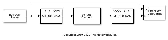
Run the slex_mil188_qam_demod model with the EbN0 of the AWGN channel block set to 6 dB. The results are saved to the base workspace variable ErrorVec in a 1-by-3 row vector. The first element contains the BER.

With EbN0 set to 6 dB, BER: 0.636

Change the EbN0 of the AWGN channel block to 10 dB. Run the model and observe the decrease in BER.

With EbN0 set to 10 dB, BER: 0.545

Ports

Input

expand all

MIL-STD-188 standard-specific QAM modulated signal, specified as a scalar, vector, or matrix. When this input is a matrix, each column is treated as an independent channel. This port is unnamed until the Var port is enabled.

Data Types: double | single
Complex Number Support: Yes

Noise variance, specified as a positive scalar or vector of positive values. When the noise variance or signal power result in computations involving extreme positive or negative magnitudes, see MIL-STD-188-110 QAM Soft Demodulation for demodulation decision type considerations.

Dependencies

To enable this port set the Noise variance source parameter to Input port.

Output

expand all

Demodulated signal, returned as a scalar, vector, or matrix. The dimensions of the demodulated signal depend on the specified Output type and Decision type parameter values. This port is unnamed on the block.

Output typeDecision typeDemodulated Signal DescriptionDimensions of Demodulated Signal
IntegerDemodulated integer values in the range [0, (M – 1)]The output signal has the same dimensions as input signal.
BitHard decisionDemodulated bitsThe number of rows in the output signal is log2(M) times the number of rows in the input signal. Each demodulated symbol is mapped to a group of log2(M) elements in a column, where the first element represents the MSB, and the last element represents the LSB.
Log-likelihood ratioLog-likelihood ratio value for each bit
Approximate log-likelihood ratioApproximate log-likelihood ratio value for each bit

M is the value of Modulation order.

Use Output data type to specify the output data type.

Parameters

expand all

To edit block parameters interactively, use the Property Inspector. From the Simulink® Toolstrip, on the Simulation tab, in the Prepare gallery, select Property Inspector.

Modulation order, M, specified as 16, 32, 64, or 256. The modulation order specifies the total number of points in the constellation of the input signal.

Constellation scaling preference, specified as:

  • As specified in standard – The block scales the constellation based on specifications in the relevant standard [1].

  • Unit average power – The block scales the constellation to an average power of 1 watt referenced to 1 ohm.

Output type, specified as Integer or Bit. To use Integer, the input signal must consist of integers in the range [0, (M – 1)]. To use Bit, the input signal must contain binary values, and the number of rows must be an integer multiple of log2(M), where M is the Modulation order.

Demodulation decision type, specified as Hard decision, Log-likelihood ratio, or Approximate log-likelihood ratio. See MIL-STD-188-110 QAM Soft Demodulation for algorithm selection considerations.

Dependencies

This parameter applies when you set Output type to Bit.

Noise variance source, specified as:

  • Property — Set the noise variance using the Noise variance parameter.

  • Input port — Set the noise variance using the Var input port.

Dependencies

This parameter applies when you set Decision type to either Log-likelihood ratio or Approximate log-likelihood ratio.

Noise variance, specified as a positive scalar or vector of positive values.

  • When specified as a scalar, that value is used on all elements in the input signal.

  • When specified as a vector, the vector length must be equal to the number of columns in the input signal. Each noise variance vector element is applied to its corresponding column in the input signal.

When the noise variance or signal power result in computations involving extreme positive or negative magnitudes, see MIL-STD-188-110 QAM Soft Demodulation for demodulation decision type considerations.

Dependencies

This parameter applies when you set Noise variance to Property and Decision type to either Log-likelihood ratio or Approximate log-likelihood ratio.

Output data type, specified as one of the acceptable values from this table. Acceptable Output data type values depend on the Output type and Decision type parameter values.

Output typeDecision typeOutput data type Options
IntegerNot applicabledouble, single, int8, uint8, int16, uint16, int32, or uint32
BitHard decisiondouble, single, int8, uint8, int16, uint16, int32, uint32, or logical
Log-likelihood ratio or Approximate log-likelihood ratioThe output signal is the same data type as the input signal.

Dependencies

This parameter applies when you set Output type to Integer or when you set Output type to Bit and Decision type to Hard decision.

Type of simulation to run, specified as Interpreted execution or Code generation.

  • Interpreted execution — Simulate the model by using the MATLAB® interpreter. This option requires less startup time, but the speed of subsequent simulations is slower than with the Code generation option. In this mode, you can debug the source code of the block.

  • Code generation — Simulate the model by using generated C code. The first time you run a simulation, Simulink generates C code for the block. The model reuses the C code for subsequent simulations unless the model changes. This option requires additional startup time, but the speed of the subsequent simulations is faster than with the Interpreted execution option.

For more information, see Simulation Modes (Simulink).

Block Characteristics

Data Types

Boolean | double | integer | single

Multidimensional Signals

yes

Variable-Size Signals

no

More About

expand all

Tips

  • For faster execution of the MIL-188 QAM Demodulator Baseband block, set the Simulate using parameter to:

    • Code generation when using hard decision demodulation.

    • Interpreted execution when using soft decision demodulation.

References

[1] MIL-STD-188-110B & C: "Interoperability and Performance Standards for Data Modems." Department of Defense Interface Standard, USA.

Extended Capabilities

C/C++ Code Generation
Generate C and C++ code using Simulink® Coder™.

Version History

Introduced in R2018b