Main Content

MIL-188 QAM Modulator Baseband

MIL-STD-188-110 B/C standard-specific quadrature amplitude modulation (QAM)

  • MIL-188 QAM Modulator Baseband block

Libraries:
Communications Toolbox / Modulation / Digital Baseband Modulation / AM
Communications Toolbox / Modulation / Digital Baseband Modulation / Standard-Compliant

Description

The MIL-188 QAM Modulator Baseband block modulates the input signal using MIL-STD-188-110 standard-specific quadrature amplitude modulation (QAM).

Examples

expand all

Apply MIL-STD-188 QAM to random data symbols, pass the modulated signal through an AWGN channel, and then plot the signal constellation.

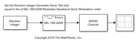
The cm_ex_mil188_qam_mod model is configured for a modulation order 16. To get desired results all blocks in the model must align their configuration to the same modulation order. The InitFcn callback defines the workspace variable, M = 16, and this variable is used to set:

The Constellation Diagram block has the Reference constellation parameter set to Custom and the Custom value parameter set to align with the modulator block's modulation setting. To see the values, open Reference Constellation in the Plot tab on the Constellation Diagram window.

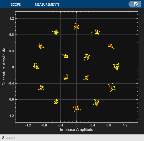
Run the model with the EbN0 of the AWGN channel block set to 20 dB, and then view the constellation diagram.

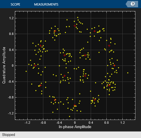
Change the EbN0 of the AWGN channel block to 10 dB. Run the model and observe the increase in noise shown in the plotted constellation diagram.

You can try running the model with a different modulation order. To adjust the modulation order you must align:

  • The Modulation order setting in the MIL-188 QAM Modulator Baseband block. To set the Modulation order for the MIL-188 QAM Modulator Baseband block select a value from the dropdown list in the block mask.

  • The value of the workspace variable M.

  • The Reference constellation in the Constellation Diagram block.

If these parameters are not aligned with each other you will notice that the reference constellation and input signal do not produce the desired constellation.

Ports

Input

expand all

Input signal, specified as a scalar, vector, or matrix. The input signal must be binary values or integers in the range [0, (M – 1)], where M is the Modulation order. This port is unnamed on the block.

Note

To process the input signal as binary elements, set the Input type parameter value to Bit. For binary inputs, the number of rows must be an integer multiple of log2(M). Groups of log2(M) bits in a column are mapped onto a symbol, with the first bit representing the MSB and the last bit representing the LSB.

Data Types: single | double | int8 | int16 | int32 | uint8 | uint16 | uint32 | Boolean

Output

expand all

MIL-STD-188 standard-specific QAM modulated signal, returned as a complex scalar, vector, or matrix. The output signal dimensions depend on the specified Input type parameter value. This port is unnamed on the block.

Input typeDimensions of Output Signal
IntegerThe output signal has the same dimensions as the input signal.
BitThe number of rows in the output signal equals the number of rows in the input signal divided by log2(M), where M is the Modulation order.

Use Output data type to specify the output data type.

Data Types: double | single

Parameters

expand all

To edit block parameters interactively, use the Property Inspector. From the Simulink® Toolstrip, on the Simulation tab, in the Prepare gallery, select Property Inspector.

Modulation order, M, specified as 16, 32, 64, or 256. The modulation order specifies the total number of points in the constellation of the output signal.

Constellation scaling preference, specified as:

  • As specified in standard – The block scales the constellation based on specifications in the relevant standard [1].

  • Unit average power – The block scales the constellation to an average power of 1 watt referenced to 1 ohm.

Input type, specified as Integer or Bit. To use Integer, the input signal must consist of integers in the range [0, (M – 1)]. To use Bit, the input signal must contain binary values, and the number of rows must be an integer multiple of log2(M), where M is the Modulation order.

Output data type, specified as double or single.

To plot the reference constellation, click the View Constellation button.

Type of simulation to run, specified as:

  • Code generation –– Simulate the model using generated C code. The first time you run a simulation, Simulink generates C code for the block. The C code is reused for subsequent simulations as long as the model does not change. This option requires additional startup time, but the speed of the subsequent simulations is comparable to Interpreted execution.

  • Interpreted execution –– Simulate the model using the MATLAB® interpreter. This option shortens startup time and has a simulation speed comparable to Code generation. In Interpreted execution mode, you can debug the source code of the block.

Block Characteristics

Data Types

Boolean | double | integer | single

Multidimensional Signals

yes

Variable-Size Signals

no

More About

expand all

References

[1] MIL-STD-188-110B & C: "Interoperability and Performance Standards for Data Modems." Department of Defense Interface Standard, USA.

Extended Capabilities

C/C++ Code Generation
Generate C and C++ code using Simulink® Coder™.

Version History

Introduced in R2018b