Sounding Reference Signal (SRS)
Sounding reference signals (SRS) are transmitted on the uplink and allow the network to estimate the quality of the channel at different frequencies.
Sounding Reference Signals
The SRS is used by the base station to estimate the quality of the uplink channel for large bandwidths outside the assigned span to a specific UE. This measurement cannot be obtained with the DRS since these are always associated to the PUSCH or PUCCH and limited to the UE allocated bandwidth. Unlike the DRS associated with the physical uplink control and shared channels the SRS is not necessarily transmitted together with any physical channel. If the SRS is transmitted with a physical channel then it may stretch over a larger frequency band. The information provided by the estimates is used to schedule uplink transmissions on resource blocks of good quality.
SRS can be transmitted as often as every second subframe (2 ms) or as infrequent as every 16th frame (160ms). The SRS are transmitted on the last symbol of the subframe.
There are two methods of transmitting the SRS:
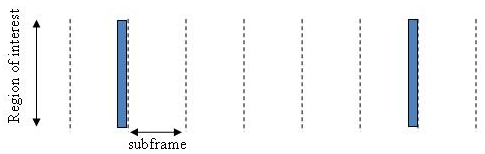
Wideband mode — one single transmission of the SRS covers the bandwidth of interest. The channel quality estimate is obtained within a single SC-FDMA symbol. However, under poor channel conditions such as deep fade and high path loss, using this mode can result in a poor channel estimate.
Non-frequency-hopping SRS
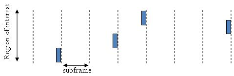
Frequency-hopping mode — the SRS transmission is split into a series of narrowband transmissions that will cover the whole bandwidth region of interest; this mode is the preferred method under poor channel conditions.
Frequency-hopping SRS
Sounding Reference Signals Generation
The sounding reference signals are generated using a base sequence denoted by . This base sequence is discussed further in Base sequence. This base sequence, used expressly to denote the SRS sequence, is defined by the following equation.
It is desirable for the SRS sequences to have small power variations in time and frequency, resulting in high power amplifier efficiency and comparable channel estimation quality for all frequency components. Zadoff-Chu sequences are good candidates as they exhibit constant power in time and frequency. However the number of Zadoff-Chu sequences is limited which makes them unsuitable for use on their own. The generation and mapping of the SRS are discussed further in this section.
Base sequence
The sounding reference signals are defined by a cyclic shift, α, of a base sequence, r.
The base sequence, r, is represented in the following equation.
The preceding equation contains the following variables.
, where is the length of the reference signal sequence.
is the base sequence group number.
is the sequence number within the group and only applies to reference signals of length greater than 6 resource blocks.
A cyclic shift in the time domain (post IFFT in the OFDM modulation) is equivalent to a phase rotation in the frequency domain (pre-IFFT in the OFDM modulation). The base sequence is cyclic shifted to increase the total number of available sequences. For frequency non-selective channels over the 12 subcarriers of a resource block it is possible to achieve orthogonality between SRS generated from the same base sequence if , where (configured for each UE by higher layers) and assuming the SRS are synchronized in time.
The orthogonality can be exploited to transmit SRS at the same time, using the same frequency resources without mutual interference. Generally, SRS generated from different base sequences will not be orthogonal; however they will present low cross-correlation properties.
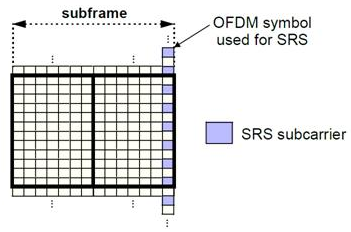
Similar to the uplink demodulation reference signals for the PUCCH and PUSCH, the SRS are time multiplexed. However, they are mapped to every second subcarrier in the last symbol of a subframe, creating a comb-like pattern, as illustrated in the following figure.
The minimum frequency span covered by the SRS in terms of bandwidth is 4 resource blocks and larger spans are covered in multiples of 4 resource blocks. This means that the minimum sequence length is 24. To maximize the number of available Zadoff-Chu sequences, a prime length sequence is needed. The minimum length sequence, 24, is not prime.
Therefore, Zadoff-Chu sequences are not suitable by themselves. Effectively, there are the following two types of base reference sequences:
those with a sequence length ≥ 48 (spanning 8 or more resource blocks), which use a cyclic extension of Zadoff-Chu sequences
those with a sequence length = 24 (spanning 4 resource blocks), which use a special QPSK sequence
SRS Grouping
There are a total of 30 sequence groups, , each containing one sequence for length less than or equal to 60. This corresponds to transmission bandwidths of 1,2,3,4 and 5 resource blocks. Additionally, there are two sequences (one for v = 0 or 1) for length ≥ 72; corresponding to transmission bandwidths of 6 resource blocks or more.
Note that not all values of m are allowed, where m is the number of resource blocks used for transmission. Only values for m that are the product of powers of 2, 3 and 5 are valid, as shown in the following equation.
The reason for this restriction is that the DFT sizes of the SC-FDMA precoding operation are limited to values which are the product of powers of 2, 3 and 5. The DFT operation can span more than one resource block, and since each resource block has 12 subcarriers, the total number of subcarriers fed to the DFT will be 12m. Since the result of 12m has to be the product of powers of 2, 3 and 5 this implies that the number of resource blocks must themselves be the product of powers of 2, 3 and 5. Therefore values of m such as 7, 11, 14, 19, etc. are not valid.
For a given time slot, the uplink reference signal sequences to use within a cell are taken from one specific sequence group. If the same group is to be used for all slots then this is known as fixed assignment. On the other hand, if the group number u varies for all slots within a cell this is known as group hopping.
Fixed group assignment. When fixed group assignment is used, the same group number is used for all slots. The group number u is the same as for PUCCH and is a function of the cell identity number modulo 30.
Group hopping. If group hopping is used, the pattern is applied to the calculation of the sequence group number.
This pattern is defined as the following equation.
As shown in the preceding equation, this group hopping pattern is a function of the slot number ns and is calculated making use of a pseudorandom binary sequence c(k), generated using a length-30 Gold code. To generate the group hopping pattern, the PRBS generator is initialized with the following value at the start of each radio frame.
For SRS with group hopping, the group number, u, is given by the following equation.
See Also
lteSRS | lteSRSIndices | lteSRSInfo | lteULResourceGrid