Compute Differential TDR and TDT
This example shows how to use RF Toolbox™ functions to calculate the time-domain reflectometry (TDR) and time-domain transmission (TDT) of a differential high-speed backplane channel.
You can use TDR and TDT waveforms to characterize high-speed channels, transmission lines, and other electrical systems.
Read Single-Ended 4-Port S-Parameters and Convert Them to Differential 2-Port S-Parameters
Use the sparameters object to extract S-parameters from the default.s4p Touchstone file. The parameters in this data file are the 50-ohm S-parameters of a single-ended 4-port passive circuit, measured at 1496 frequencies ranging from 50 MHz to 15 GHz. Next, extract the single-ended four-port S-parameters from the data object.
filename = "default.s4p";
backplane = sparameters(filename);
data = backplane.Parameters;
freq = backplane.Frequencies;
z0 = backplane.Impedance;
Use the matrix conversion function s2sdd to convert the 4-port S-parameters to 2-port differential S-parameters.
diffdata = s2sdd(data);
diffsparams = sparameters(diffdata,freq,2*z0);
z0differential = diffsparams.Impedance;
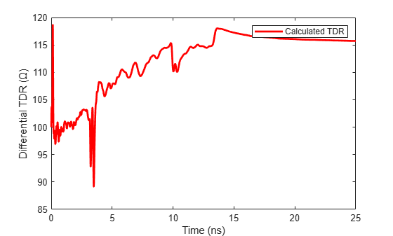
Calculate and Plot the Differential TDR
TDR is the time-domain reflected signal from any impedance discontinuities within a circuit. First, extract the differential S11 (reflected signal in the frequency domain) data using the rfparam function. Convert the S11 data to a time-domain signal by creating a rational function of the data using the rational function. Compute the TDR Signal using the stepresp function of the rfmodel.rational object.
s11 = rfparam(diffsparams,1,1);
s11fit = rational(freq,s11);
Ts = 5e-12;
N = 5000;
Trise = 5e-11;
[tdr,tdrT] = stepresp(s11fit,Ts,N,Trise);
Calculate the impedance over time using the gamma2z function and plot the calculated TDR impedance versus time.
zLt = gamma2z(tdr, z0differential);
figure
plot(tdrT*1e9,zLt,'r',LineWidth=2)
ylabel("Differential TDR (Ω)")
xlabel("Time (ns)")
legend("Calculated TDR")
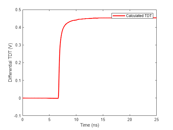
Calculate and Plot Differential TDT
TDT is the time-domain transmitted voltage signal from an input in an electrical circuit. Use the rational function perform rational fitting on the TDT frequency data, then use the stepresp function to compute the TDT signal. Calculate the final TDT voltage signal by using the input voltage (S-parameters are normalized to 1 V by the equipment). Plot the calculated TDT.
s21 = rfparam(diffsparams,2,1);
s21fit= rational(freq,s21);
Ts = 5e-12;
N = 5000;
Trise = 5e-11;
[tdt,tdtT] = stepresp(s21fit, Ts, N, Trise);
Vin = 1;
tdtV = Vin*tdt/2;
figure
plot(tdtT*1e9,tdtV,'r',LineWidth=2)
ylabel("Differential TDT (V)")
xlabel("Time (ns)")
legend("Calculated TDT")
References
[1] Zeng. R, J. Sinsky. "Modified Rational Function Modeling Technique for High Speed Circuits." MTT-S Int. Microwave Symp. Dig., San Francisco, CA, June 11-16, 2006.
[2] A. S. Ali, R. Mittra. "Time-Domain Reflectometry using Scattering Parameters and a De-Embedding Application" Technical Report, Electromagnetic Communication Laboratory Report No. 86-4, May 1986.