Simulation Parameters Used in Serial Link Design
You can set parameters that control how a simulation is run in Serial Link Designer using the Simulation Parameters dialog from the Setup > Simulation Parameters menu item. This dialog contains a table with parameters, their values, and the part of the analysis flow they affect. You can sort the columns by clicking on the table headers.
Simulation Parameter Definitions
| Parameter | Description |
|---|---|
| Samples Per Bit | Number of time steps in a bit time. Defines the time step used in the Serial Link Designer “.tran” statement. |
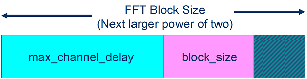
| Max Channel Delay | Maximum length of the channel impulse response supplied by the user. This value is also used in FFT block size calculation that defines the message length used for statistical analysis. For more information, see Determining FFT Block Size. |
| Target BER | Array of bit error rates (BER) to measure eye height and width. The array
is sorted from the smallest to the largest. If fewer than four values are entered
the results will include four values. The additional values are created by
multiplying the last value by |
| Minimum Ignore Bits | Start time for Time Domain waveform analysis. Allows time for all of the AMI models to reach steady state. This is used if models do not define Ignore Time set in the AMI model, or the defined Ignore Time is less than this value. The larger of this value or a value from a model is used as the Ignore Bits for the analysis. |
| Max Input Frequency | Maximum frequency valid for the network model, determined by the maximum frequency for which S parameters are available. This frequency can be limited or extended by the user. For more information, see Max Input Frequency. |
| Max Output Frequency | Maximum frequency output for transfer function and S parameters describing the end to end passive electrical interconnect. For more information, see Max Output Frequency. |
| S-Param Frequency Step | Frequency step size for S-parameters output from the Serial Link Designer app. The value of this parameter controls the behavior of the Serial Link app:
|
| Record Start | Time to start saving waveforms in a Time Domain simulation. |
| Record Bits | Number of bits of the waveform to save. |
| Time Domain Stop | The stop time of the Time Domain simulation. |
| Block Size | The number of samples in a single waveform segment in a Time Domain simulation. This sets the granularity of the parameter outputs returned by AMI models. Also used in determining FFT block size. |
| Output Clock Ticks | If yes, then Time Domain simulation will output the recovered clock ticks to a file. |
| STATify | Control how statistical techniques are applied to Time Domain simulations and Getwave-only models. The values are:
|
| Results Storage Control | Determine which results to store. |
| Time Domain Crosstalk Mode | How to account for crosstalk in Time Domain simulation.
|
| SPICE Rise Time | Transition time from 0 to 100 percent of the stimulus input to the Driver. |
| SPICE Sample Interval | The time step used in the SPICE ".tran" statement. The value is an integer greater than 1 or units of time in seconds. If the value is an integer then it is the number of time steps in a bit time. |
| SPICE Buffer Models |
|
| SPICE Ignore Bits | The time before the start of the SPICE step in the step response simulation. It is either in UI or in units of seconds. |
| SPICE Step Stop | Stop time of SPICE step response simulation. |
| SPICE Time Domain Stop | Stop time of SPICE Time Domain simulation. |
| Include IBIS Package | Include (Yes) or do not include (No) IBIS Package model as defined in the IBIS file. |
| Conductor Roughness | Surface roughness of conductors in microns (RMS). Used for lossy transmission line models created outside Serial Link app. |
| NC/TD Simulation Mode | Simulator used for network characterization (NC) and time domain (TD) phases of channel analysis. Mode used is based on modes supported by models.
|
| Tx Spectral Table | Specifies the spectral table to use for the transmitter. The list box shows the spectral tables that have been imported into the project libraries. |
| Rx Spectral Table | Specifies the spectral table to use for the receiver. The list box shows the spectral tables that have been imported into the project libraries. |
| Spectral Analysis Resolution BW | Resolution bandwidth of clock spectral analysis. |
| Clock Analysis | Clock phase noise spectral density analysis and output. |
Max Input Frequency
Maximum frequency valid for all network models, determined by the maximum frequency for which S parameters are available. This frequency can be limited or extended by the user. The value of this parameter controls the behavior of the Serial Link app:
Auto or Zero — This option is an automatic mode. Serial Link app engine calculates the maximum frequency from a combination of the sample interval and the S-Parameter blocks in the netlist. The app then chooses the highest frequency for which all the circuit elements can be defined. If there are no S-Parameter blocks, then the highest frequency is defined by the equation:
Non-Zero Value — Use this value or the maximum frequency that defines all the S-Parameters whichever is smaller as the maximum frequency of the network model. The frequency value effects the TDR rise time via the following equation:
The default is Auto.
Max Output Frequency
Maximum frequency output for transfer function and S parameters describing the end to end passive electrical interconnect. The value of this parameter controls the behavior of the Serial Link app as follows:
Auto or Zero — This option is an automatic mode. Serial Link app sets the output frequency to , where DR is the highest data rate of any TX in the analysis. The default is Auto.
Non-Zero Value — Use this value for the maximum frequency.
Determining FFT Block Size
Two of the parameters, Max Channel Delay and Block Size, determine the FFT block size used in network characterization and statistical analysis. The actual FFT block size is rounded up to the nearest power of two.
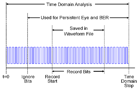
Time Domain Start and Stop Parameters
The time domain parameters that control the start and stop of the simulation are:
Time Domain Stop
Record Start
Record Bits
Minimum Ignore Bits
This figure demonstrates the relationship of several Time Domain simulation parameters.