Passive Cell Balancing

Libraries:
Simscape /
Battery /
BMS /
Cell Balancing
Description
This block implements a passive battery cell balancing algorithm. The passive cell balancing technique keeps a similar state-of-charge value in all cells by dissipating the excess charge in a bleed resistor.
The value at the u input port can be cell voltages or cell
state-of-charge (SOC) values. The Enable input port acts as a
trigger for the balancing procedure. When Enable is
1, the block starts balancing the battery until the battery is
fully balanced.
This block supports single-precision and double-precision floating-point simulation.
Note
To enable inherited single-precision floating-point simulation, the data type of all
inputs and parameters, except for the Sample time (-1 for
inherited) parameter, must be single.
You can switch between continuous and discrete implementations of the block by using
the Sample time (-1 for inherited) parameter. To configure the
block for continuous time, set the Sample time (-1 for
inherited) parameter to 0. To configure the block for
discrete time, set the Sample time (-1 for inherited)
parameter to a positive, nonzero value, or to -1 to inherit the
sample time from an upstream block.
Note
Continuous-time implementation of this block works only in a double-precision floating-point simulation. If you provide single-precision floating-point parameters and inputs, this block casts them to double-precision floating-point values to prevent errors.
This diagram shows the structure of the block:
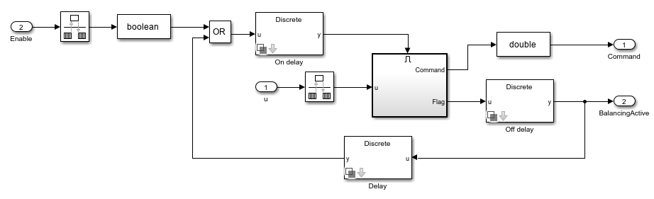
Equations
When the value at the Enable input port is 1, the
block starts balancing the battery until the battery is fully balanced. To balance
the battery, the algorithm discharges some of the cells until their voltage or
state-of-charge is equal to the voltage or state-of-charge of the cell with the
lowest value.
The Command output port specifies the balancing command as a vector of elements equal to 0 or 1. This equation determines each element of Command:
where Threshold is the value of Threshold for balancing parameter, HysteresisBand is the value of the Hysteresis band for switching balancing off parameter, and Commandold is the command at the previous step.
To specify the data type of the Command output port, use the Command Data Type parameter.
The BalancingActive output port is true if any cell of the battery exceeds the threshold value.
Examples
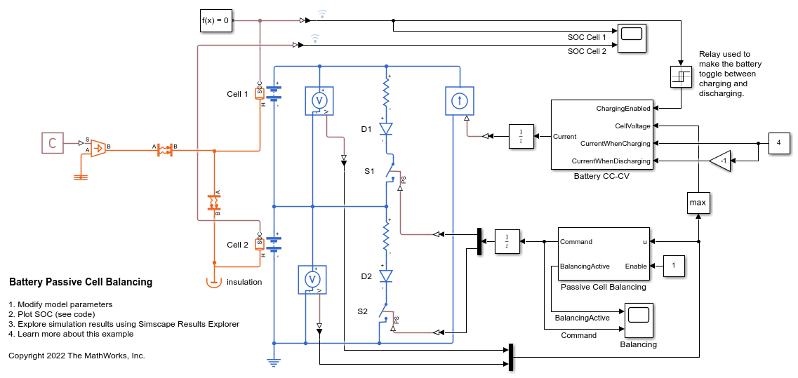
Battery Passive Cell Balancing
Balance a battery with two cells connected in series by using a passive cell balancing algorithm. The initial state-of-charge (SOC) for the two cells are equal to 0.7 and 0.75. The balancing procedure depends on the cell voltages. Alternatively, you can use the SOC values for balancing. When the balancing is active, a bleeding resistor switches on to bleed the cells with higher charge. You can use the objects and functions in the Battery Pack Model Builder to generate more complex battery packs.
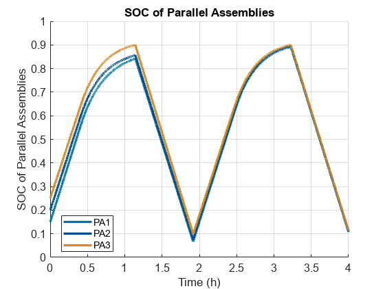
Charge and Discharge Battery Module with Passive Balancing
Perform a cyclic charge and discharge cycle on a battery module while balancing the voltages of the module parallel assemblies.
Ports
Input
Output
Parameters
Main
Threshold that the block uses for balancing.
Since R2023b
Hysteresis band for switching off the passive cell balancing. The value of this parameter must be less than or equal to the value of the Threshold for balancing parameter.
Time delay before activating the cell balancing, in seconds.
Time delay after the block completes the balancing procedure, in seconds.
Time between consecutive block executions. During execution, the block produces outputs and, if appropriate, updates its internal state. For more information, see What Is Sample Time? and Specify Sample Time.
For inherited discrete-time operation, specify this parameter as -1.
For discrete-time operation, specify this parameter as a positive real
number. For continuous-time operation, specify this parameter as
0.
If this block is in a masked subsystem or a variant subsystem that allows you to switch between continuous operation and discrete operation, promote the sample time parameter. Promoting the sample time parameter ensures correct switching between the continuous and discrete implementations of the block. For more information, see Promote Block Parameters to a Mask.
Signal Attributes
Specify the data type of the Command output. You
can specify the type directly or you can express it as a data type
object such as Simulink.NumericType.
Click the Show data type assistant button ![]() to display the Data Type
Assistant, which helps you set the data type attributes.
For more information, see Specify Data Types Using Data Type Assistant.
to display the Data Type
Assistant, which helps you set the data type attributes.
For more information, see Specify Data Types Using Data Type Assistant.
References
[1] Daowd, Mohamed, Noshin Omar, Peter Van Den Bossche, and Joeri Van Mierlo. "Passive and active battery balancing comparison based on MATLAB simulation." 2011 IEEE Vehicle Power and Propulsion Conference (October 2011): 1-7. https://doi.org/10.1109/VPPC.2011.6043010.
Extended Capabilities
Version History
Introduced in R2022b