Contenuto principale

Sensor Models for Unreal Engine Simulation

Simulink® 3D Animation™ provides sensor models that generate synthetic data from the 3D environment. A sensor is an actor in the 3D environment that models a sensor to generate information about the 3D environment. You can view the 3D environment in the Simulation 3D Viewer through the MATLAB® and Simulink interfaces of Simulink 3D Animation. The simulation environment is visualized using the Unreal Engine® from Epic Games®.

Sensor Data Generation

Sensor models use either ray tracing or rendering of the Unreal Engine to generate sensor data from the 3D environment.

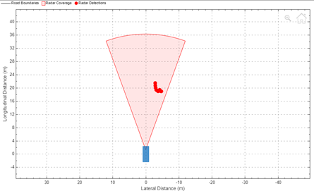
  • Sensor models that use ray tracing interrogate the environment with directed rays that intersect objects. The rays from the sensor detects intersections as the ray travels through the scene.

  • Sensor models that use rendering return images with photorealism, depth, and semantic data from the 3D environment for object detection.

The sensor returns data from the 3D environment to MATLAB or Simulink according to the sample time of the sensor. Due to the lock-step mechanism, MATLAB or Simulink provides the sensor data as output in the next simulation time step. Therefore, the sensor data output is delayed by one time step.

Sensor Models in Simulink 3D Animation

You can create sensors for 3D simulation using Simulation 3D blocks in Simulink or sim3d objects and functions in MATLAB. The table summarizes the sensor blocks and classes that you can use for 3D simulation.

SensorDescriptionSensor Data

Simulation 3D Camera Get

sim3d.sensors.IdealCamera

  • Provides a pinhole camera model to generate a visual representation of the 3D environment.

  • You can set the image size and horizontal field of view.

  • This sensor model uses rendering to generate sensor data.

  • For more details, see What Is Camera Calibration? (Computer Vision Toolbox)

  • View the image data using the To Video display block in Simulink or the image function in MATLAB.

    Camera display

Note

The To Video display block requires Computer Vision Toolbox™.

Simulation 3D Camera

sim3d.sensors.Camera

  • Provides a pinhole camera model with a lens.

  • Field of view of up to 150 degrees.

  • You can set various parameters, including focal length, distortion coefficients, and skew.

  • This sensor model uses rendering to generate sensor data.

  • For more details, see What Is Camera Calibration? (Computer Vision Toolbox)

  • View the image data using the To Video display block in Simulink or the image function in MATLAB.

    Camera display

  • View the depth data using the To Video Display block in Simulink or the imagesc function in MATLAB. You can visualize depth data in grayscale, with light shades indicating farther objects and darker shades indicating closer objects.

    Depth display

  • View the semantic data using the To Video display block in Simulink or the image function in MATLAB. You can use the semantic data to identify and classify objects, regions, and structures within the captured images.

    Semantic segmentation display

    For the scenes in Unreal Engine, you can use a colormap to define the label IDs for the objects in the scenes. For more information on adding label IDs, see Apply Labels to Unreal Scene Elements for Semantic Segmentation and Object Detection.

Note

The To Video display block requires Computer Vision Toolbox.

For an example on how to visualize image, depth, and semantic data, see Import RoadRunner Scene into Unreal Engine Using Simulink.

Simulation 3D Fisheye Camera

sim3d.sensors.FisheyeCamera

  • Provides a fisheye camera model proposed by Scaramuzza [1]. The model provides a wide angle effect and captures larger field of view.

  • Field of view of up to 195 degrees.

  • You can set various parameters, including distortion center, projection function, and stretch matrix.

  • You can also set the intrinsic parameters for your camera to capture up to 360 degrees.

  • This sensor model uses rendering to generate sensor data.

  • View the image data using the To Video display block in Simulink or the image function in MATLAB.

    Fisheye camera display

Note

  • The Simulation 3D Fisheye Camera block or sim3d.sensors.FisheyeCamera object requires Computer Vision Toolbox.

  • the To Video display block requires Computer Vision Toolbox.

Simulation 3D Ray Tracer

sim3d.sensors.RaytraceSensor

  • Provides information about the 3D environment in specified directions.

  • Optionally includes information about ray reflections.

  • You can set the ray origin relative to sensor location, ray directions, ray lengths, and number of bounces.

  • This sensor model uses ray tracing to generate sensor data.

  • You can visualize the rays from the sensor during the simulation. Rays generated from the sensor are displayed as red rays. Rays reflected from the target are displayed as green rays. The area of intersection on the target surface is displayed as a blue box.

    Rays from ray trace sensor in the 3D environment.

    You can also display or plot additional target detection data, including whether a valid hit occurred and the exact hit location.

Simulation 3D Lidar

sim3d.sensors.Lidar

  • Provides point cloud data of the 3D environment with the specified field of view and angular resolution.

  • This sensor model uses rendering to generate sensor data.

  • The sensor model uses the scan pattern of a rotating lidar sensor.

  • View the point cloud data using the pcplayer function, the pcshow function, or the scatter3 function.

    Point cloud data

    Note

    The pcplayer and pcshow functions require Computer Vision Toolbox.

  • You can also display additional target detection data, including distance and reflectivity of the target.

Simulation 3D Ultrasonic Sensor

sim3d.sensors.UltrasonicSensor

  • Provides an ultrasonic sensor model.

  • Set the detection range to detect objects in the field of view or measure range.

  • This sensor model uses ray tracing to generate sensor data.

  • You can set the sensor range and display whether a detectable object is present within the field of view and the range of the target.

  • In Simulink, you can set the detection ranges by specifying [minDetOnlyRange minDistRange maxDistRange] and use a scope to display the sensor output.

    The sensor output, Has Object is 1 when the target is within detection range. The sensor output Has Range is 1 when the target is within the valid distance range. The sensor output Range displays the actual distance only in the valid range zone.

    Scope display of Simulation 3D Ultrasonic sensor data.

Simulation 3D Ultrasonic Array

  • Provides an array of ultrasonic sensors.

  • You can tune the acoustic parameters like frequency, sampling frequency, pulse width, gain, and speed.

  • You can set the translation, rotation, and field of view of the array. You can also set the translation, rotation, and detection range for each sensor in the array.

  • This sensor model uses ray tracing to generate sensor data.

  • You can set the sensor range and display whether a detectable object is present within the field of view and the range of the target.

  • In Simulink, you can set the detection ranges by specifying [minDetOnlyRange minDistRange maxDistRange].

    The sensor output, Has Object is 1 when the target is within detection range. The sensor output Has Range is 1 when the target is within the valid distance range. The sensor output Range displays the actual distance only in the valid range zone.

    Scope display of Simulation 3D Ultrasonic sensor data.

Simulation 3D Radar Data Generator

  • Provides a detection-level RADAR model that generates clustered, unclustered, and track data.

  • You can add random noise and false alarms to the radar data to simulate real-time scenarios.

  • This sensor model only provides detections.

  • This sensor model uses ray tracing to generate sensor data.

  • You can display or plot detections including clustered detections and tracks to predict the object track. You can also visualize the target detections using the Bird's-Eye Scope.

    Simulation 3D Radar Data Generator data using Bird's eye scope.

Note

  • Simulating models with the Simulation 3D Radar Data Generator block requires Radar Toolbox.

  • Bird's-Eye Scope requires Automated Driving Toolbox™.

References

[1] Scaramuzza, D., A. Martinelli, and R. Siegwart. "A Toolbox for Easy Calibrating Omnidirectional Cameras." Proceedings to IEEE International Conference on Intelligent Robots and Systems (IROS 2006). Beijing, China, October 7–15, 2006.

See Also

| | | | | | | | | | | | | | | |

Topics