Gain-Scheduled PID Autotuning Torque Control for a Nonlinear PMSM
This example shows how automatically tune the direct and quadrature axis current loops for nonlinear PMSM using the Gain-Scheduled PID Autotuner in Simulink® Control Design™ library.
Model Overview
This example uses the nonlinear Interior-PMSM model from the example Field-Weakening Control (with MTPA) of Nonlinear PMSM Using Lookup Table (Motor Control Blockset). The nonlinearities are modeled using a lookup table (LUT) for a nonlinear permanent magnet synchronous machine (PMSM) based on finite element analysis (FEA).
Open the model.
mcb_pmsm_nonlin_fwc_data
      model: 'JMAG 1kW design'
         sn: 'RTML-004'
          p: 2
         Rs: 0.2200
          B: 2.6369e-04
          J: 2.7000e-05
         Ld: 0.0047
         Lq: 0.0078
    I_rated: 10
     FluxPM: 0.0455
     N_base: 3588
      N_max: 16815
    T_rated: 1.5933
        model: 'hypothetical'
         V_dc: 100
      R_board: 0
    ISenseMax: 40
    V_base: 57.7350
    I_base: 40
    N_base: 3588
    P_base: 3.4641e+03
    T_base: 5.4600
mdl = 'mcb_pmsm_nonlin_fwc';
open_system(mdl);
The model also contains a Change Operating Points block, found in Simulink Control Design, to move the motor between operating speeds instead of relying on manual control for the speed, torque, and battery voltage. In order to better control the nonlinear PMSM in this example, both the direct and quadrature axis current controllers are changed to use proportional and integral gains that change based on the motor speed (gain scheduling).
The gains of the direct and quadrature axis current controllers are set up to only use a single set of gains throughout the operating speed range of the motor. In order to tune the gains, the example uses the Gain-Scheduled PID Autotuner block. This block allows for the implementation of gain-scheduling and provides a way to both tune the gains at multiple operating conditions and store the gains for use elsewhere in the model or system.
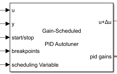
The autotuning workflow for this block is similar to the Closed-Loop PID Autotuner. The Gain-Scheduled PID Autotuner block allows you to tune one PID controller at a time. It injects perturbation signals at the plant input and measures the plant output during a closed-loop experiment. When the experiment stops, the block computes PID gains based on the plant frequency responses estimated at a small number of points near the desired bandwidth. The tuned PID gains are stored and the existing gain array, if available, is updated at the corresponding value of the scheduling variable (by default the scheduling variable is the same as the plant output). The Gain-Scheduled PID Autotuner block will also automatically determine the current PID gains based on the current value of the scheduling variable and output the corresponding gains for use in a PID Controller.
Adding PID Gain-Scheduling Blocks
The Gain Scheduled PID Autotuner is added to the model after the PID Controller and before the plant input. When not enabled (start/stop signal is 0) the autotuner will be a passthrough from the input to the output and output the PID gains corresponding to the value of the scheduling variable. This example implements gain scheduling and performs autotuning on two different controllers, the direct and quadrature axis current controllers, so two separate Gain-Scheduled PID Autotuner blocks are required. However, this example uses the same settings for each of the two autotuner blocks. Shown below is the PI Controller subsystem for the direct axis current controller.

As shown in the figure, the Gain-Scheduled PID Autotuner is inserted directly after the PID Controller block and connected with the relevant signals. The gains from the Gain Scheduled PID Autotuner are output and fed back to the PID Controller block. The I gain is multiplied by the sample time before use in the PID Controller block as the block uses I*Ts instead of just I. The gains that are output from the block are delayed by a single sample due to an algebraic loop being formed otherwise (note that if using the Data Store Memory option of the Gain-Scheduled PID Autotuner block these delays are not necessary as there is an inherent delay in reading/writing from/to memory).
To set up the Gain-Scheduled PID Autotuner blocks used in this example, the autotuning settings on the Autotuner tab are:
Controller Type: PI to match the PID controller
Bandwidth: 5000 rad/sec to allow the transitions to complete in roughly 400 us
Phase Margin: 80 degrees to reduce overshoot
Signal Amplitudes: 0.4 to allow for sufficient perturbation amplitudes and keep away from down stream limits
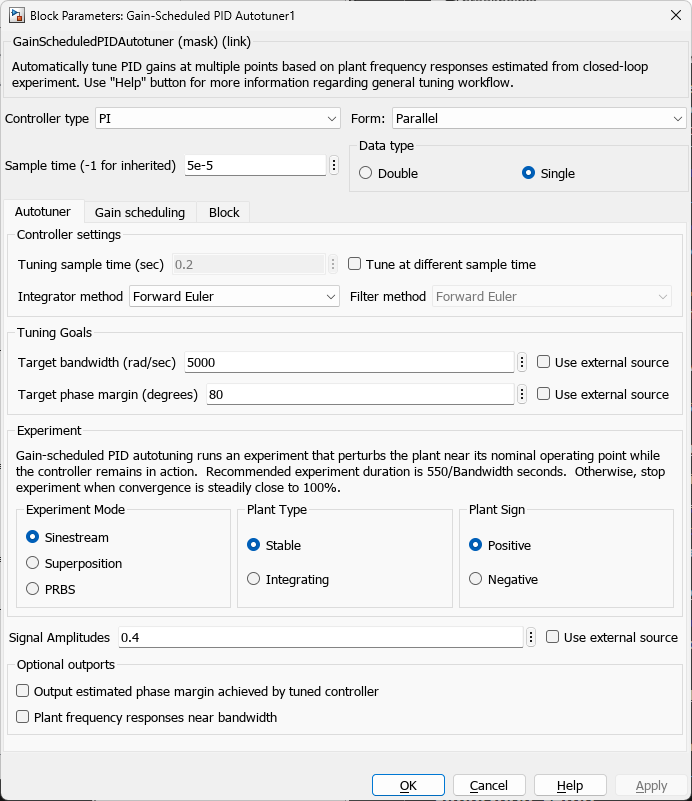
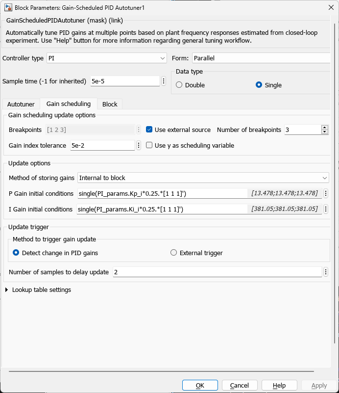
Next, the block is configured gain scheduling on the Gain scheduling tab as follows:
Breakpoints: set to [0.1 0.5 0.9] for 3 different speeds over the speed range
P Gain initial conditions: PI_params.Kp_i*0.25.*[1 1 1]'. This is the default value used for the P gain but detuned to allow for proper autotuning
I Gain initial conditions: PI_params.Ki_i*0.25.*[1 1 1]'. This is the default value used for the I gain but detuned to allow for proper autotuning
The model is set up to move between the 3 different speeds, performing autotuning first on the direct axis current controller then the quadrature axis current controller at each speed using the Change Operating Point block.

The Change Operating Point replaces the system inputs for speed, battery voltage and torque but still allows for manual operation when not performing autotuning. The entire autotuning process can be disabled by setting the enable constant to 0. When this is done the knobs and slider on the model root can be used to control the motor without autotuning being performed, however, gain-scheduling will still be enabled.

As shown in the above image, the battery voltage and torque reference are constants connected to the slider and dial, respectively, on the top level of the model. The speed reference shown here is not used when the model is configured to perform autotuning. In the next section the setup of the Change Operating Points block is set up for autotuning.
Simulation Setup
As mentioned in the previous section, the Change Operating Points block is used to move the motor between the three different operating speeds and perform autotuning on both the direct and quadrature axis current controllers at each of the operating speeds. In order to only tune one of the controllers at a time a switch is used in the Current Controllers subsystem to only enable autotuning when the respective controller loop is desired to be tuned. This signal is generated through the use of the Change Operating Points block using its SystemInput_2 field in the block dialog box.
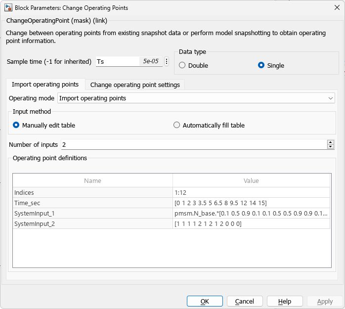
The Change Operating Points block is set up to repeat the initial transient at the end to allow for a comparison before and after autotuning the gains for gain scheduling.
In order to begin the autotuning process for each controller, the Change Operating Points block is configured to begin autotuning at predetermined times: [3 4 6 7 9 10] seconds. The entire autotuning process at each speed for each controller takes 500 ms as configured on the Change Operating Points block Change Operating Point Settings tab.
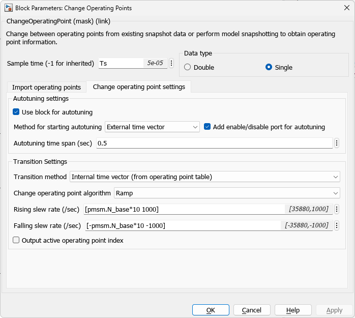
The value of 500 ms is chosen to give sufficient time for the plant estimate to complete for a chosen bandwidth of 5000 rad/sec and to allow the transients associated with the perturbations to disappear in order to properly update the gain arrays at the given speed.
Gain-Scheduled Autotuning
In the previous sections the simulation was set up to perform the autotuning process for both the direct and quadrature axis currents. The battery voltage and load torque are held constant for all operating speeds at 100 and 0.15, respectively. After simulating the model the results from before the autotuning and after can be plotted together to view the effects of gain-scheduling on the overall system response (speed feedback).
% Simulate the model
simOut = sim(mdl);
model: 'JMAG 1kW design'
sn: 'RTML-004'
p: 2
Rs: 0.2200
B: 2.6369e-04
J: 2.7000e-05
Ld: 0.0047
Lq: 0.0078
I_rated: 10
FluxPM: 0.0455
N_base: 3588
N_max: 16815
T_rated: 1.5933
model: 'hypothetical'
V_dc: 100
R_board: 0
ISenseMax: 40
V_base: 57.7350
I_base: 40
N_base: 3588
P_base: 3.4641e+03
T_base: 5.4600
% Plot the results from autotuning
idx = round([0.5 2.9 13.55 15.9975]./Ts_speed) + 1;
Time_noGS = simOut.logsout{1}.Values.Time(idx(1):idx(2))-simOut.logsout{1}.Values.Time(idx(1));
SpeedFdbk_noGS = simOut.logsout{1}.Values.Data(idx(1):idx(2));
Time_wGS = simOut.logsout{1}.Values.Time(idx(3):idx(4))-simOut.logsout{1}.Values.Time(idx(3));
SpeedFdbk_wGS = simOut.logsout{1}.Values.Data(idx(3):idx(4));
figure;
plot(Time_noGS,SpeedFdbk_noGS,Time_wGS,SpeedFdbk_wGS)
legend('No GS', 'With GS','Location','southeast')
grid on
title({'Step Response Comparison of Speed'; 'with and without Gain Scheduling'})
xlabel('Time [sec]')
ylabel('Speed Feedback [-]')
![Figure contains an axes object. The axes object with title Step Response Comparison of Speed with and without Gain Scheduling, xlabel Time [sec], ylabel Speed Feedback [-] contains 2 objects of type line. These objects represent No GS, With GS.](../../examples/slcontrol/win64/GainScheduledPIDAutotuningNonlinearPMSMExample_09.png)
As shown in the plot, there is reduced overshoot and settling time when using the tuned gains from gain-scheduling versus before.
Summary
This example showed how to implement and tune gain-scheduled PID controllers for a nonlinear PMSM using the Gain-Scheduled PID Autotuner and Change Operating Points blocks from the Simulink Control Design library. Presently, the Gain-Scheduled PID Autotuner block supports only a single scheduling variable by which to change the PID gains. Using more than one scheduling variable allows for greater flexibility for the kind of nonlinear systems shown in this example. For instance, using 3 scheduling variables and varying speed alongside the battery voltage and torque would allow for robust gain-scheduled control over a large operating region.