Import Data for Parameter Estimation
Create Experiment
Before you begin data import, create an experiment. Simulink® Design Optimization™ software provides an app for setting up the estimation session.
To create an estimation session:
At the MATLAB® prompt, obtain the nonlinear idle speed model of an automotive engine by typing:
openExample('sldo/EngineIdleSpeedModelExample')
The model contains the Inport block
BPAVand Outport blockEngine Speedfor importing input and output data, respectively. To learn more, see Model Requirements for Importing Data.In the Simulink model window, open the Parameter Estimator by selecting Apps > Parameter Estimator.

You can organize the estimation and validation tasks inside Experiments under the data browser panel on the left. You can assign each experiment to an estimation task or validation task.
To create an experiment, click the New Experiment button.

This creates an experiment called
Expunder Experiments. To change the name of the experiment, click and type the new name. Call itNewData.Note
The Simulink model must remain open to perform parameter estimation tasks.
Time-Domain Data
Experiments are collections of signal data, specifically input and output signal data. After you create an experiment, as described in Create Experiment, you can import data into your experiment from various sources including MATLAB® variables, MAT-files, Excel® files, or comma-separated-value files.
To import data into your experiment, right-click the experiment and select Edit. Doing so opens the Edit Experiment dialog box where you can define the signals contained in the experiment.

For example, the rows in the Inputs section of the editor
correspond to Inport block BPAV in the
engine_idle_speed model.
The rows in the Outputs section correspond to Outport block
Engine Speed. You can import signal data from files or MATLAB
workspace.
Note
The Simulink model must contain an Inport block, Outport block, logged signals, or Simscape™ blocks to enable importing data. For more information, see Model Requirements for Importing Data. To select more output signals to specify data for, click Select Measured Output Signals in the Outputs panel.
The idle-speed model of an automotive engine contains the measured data stored in
the iodata array in the workspace. The array contains two
columns: the first for input data, and the second for output data. The time data is
in the time array in the workspace. To import the input data, you
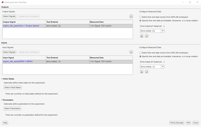
can construct a time and data array. To do so, in the Inputs
section, first select Specify time and data as timetable, timeseries, or
in array notation. Then, in the text box type
[time,iodata(:,1)].

To import the output data, in the Outputs
section, select Specify time and data as timetable, timeseries, or in
array notation. Then, in the text box type
[time,iodata(:,2)].
You can view the data by clicking ![]() .
.
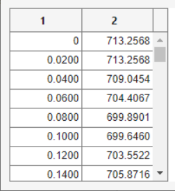
The input data should look like this:

Output data should look like this:

After importing the data for the experiment, the Edit Experiment dialog box looks like this:

To import data from a file, click the ![]() button.
button.
To learn more about the Edit Experiment dialog box, see Edit Experiment Data.
Time-Series Data
Time-series data is stored in time-series objects. For more information, see Time Series Objects and Collections.
When you import input data from a time-series object, t, for
parameter estimation, you must specify the time vector and data as
[t.time,t.inputdata] in the Inport signal dialog box.
Similarly, to import output data, you must specify the time vector and data as
[t.time,t.outputdata] in the Outport signal dialog box. For
more information on how to import data into the experiment, see Time-Domain Data.
Complex Data
Complex-valued data is data whose value is a complex number.
For example, a signal with the value 1+2j is complex. You can use
complex data to estimate parameters of electrical systems, such as the magnitude and
phase.
Note
You must sample the real and imaginary parts of the data as a function of the same time vector.
To use complex data for parameter estimation:
Split the data into two data sets that contain the real and imaginary parts. To split the data, use the MATLAB functions
real, andimag.Create two signals, one for the real part and one for the imaginary part for the Inport or Outport block.
Select both signals in the experiment editor.
Import the data to the corresponding signal as described in Time-Domain Data.