Vehicle Systems
Use these examples to learn how to implement machines and controls for automotive, marine, and aerospace systems.
Featured Examples
Control Torque of IPMSM Inside Axle-Drive EV in DQ Frame
Models an interior permanent magnet synchronous machine (IPMSM) propelling a simplified axle-drive electric vehicle. The example controls and simulates the torque in the rotor direct-quadrature (DQ) reference frame. The IPMSM operates in both motoring and generating modes. A fixed-ratio gear-reduction model implements the vehicle transmission and differential. The Vehicle Controller subsystem converts the driver inputs into a relevant torque command. The Drive Controller subsystem controls the torque of the IPMSM. The control algorithm is implemented in continuous time. To simulate this model faster, this example uses a variable-step solver. The Scopes subsystem contains scopes that allow you to see the simulation results.
- Since R2025a
- Open Model
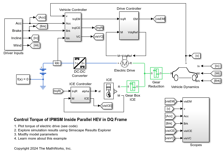
Control Torque of IPMSM Inside Parallel HEV in DQ Frame
Models a simplified parallel hybrid electric vehicle (HEV). An interior permanent magnet synchronous machine (IPMSM) and an internal combustion engine (ICE) provide the vehicle propulsion. This example controls and simulates the torque in the rotor direct-quadrature (DQ) reference frame. The IPMSM operates in both motoring and generating modes. A fixed-ratio gear-reduction model implements the vehicle transmission and differential. The Vehicle Controller subsystem converts the driver inputs into torque commands. A Stateflow® chart implements the vehicle control strategy. The ICE Controller subsystem controls the torque of the combustion engine. The EM Controller subsystem controls the torque of the IPMSM. To simulate this model faster, this example uses a variable-step solver. The Scopes subsystem contains scopes that allow you to see the simulation results.
- Since R2025a
- Open Model
Automotive Alternator Charging a Battery
How alternator behavior can be abstracted to a DC model that simulates efficiently. This test harness first ramps the alternator speed linearly from zero to a typical idle speed of 900 RPM. When the generated voltage is sufficient to overcome the forward voltage drop associated with the rectifier diodes, the battery charging current starts to ramp up. The test harness then ramps up the speed to 5000 RPM, and the alternator has to back off the field voltage to maintain the regulated voltage. The model captures the increase in stator resistance as the alternator heats up, this reducing device performance
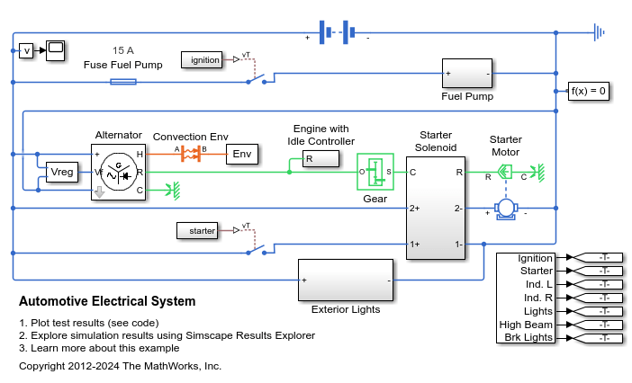
Automotive Electrical System
A simplified dynamic model of an automotive electrical system. The model contains electrical, mechanical, and thermal systems, and is able to simulate the effect of engine starting on the electrical network.
DC Fast Charger for Electric Vehicle
Models a DC fast charging station connected with the battery pack of an Electric Vehicle (EV).
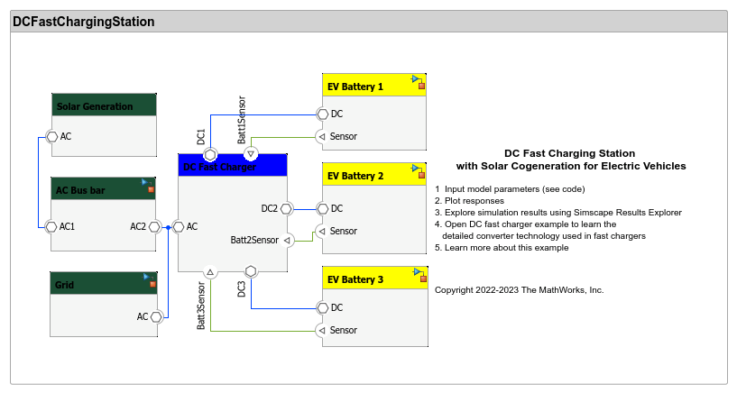
DC Fast Charging Station for Electric Vehicles with Solar Cogeneration
Models a DC fast charging station with solar cogeneration connected with the three battery packs of electric vehicles (EV).
Detailed Battery Electric Vehicle (BEV) Model
Design a battery electric vehicle (BEV) using high-fidelity models of vehicle components. You can use this model to perform detailed analysis at the component level. You can download this model in MATLAB® or access it from MATLAB Central File Exchange and GitHub®.
- Since R2023b
- Open Live Script
Electric Engine Dyno
Model an electric vehicle dynamometer test. The test environment contains an asynchronous machine (ASM) and an interior permanent magnet synchronous machine (IPMSM) connected back-to-back through a mechanical shaft. Both machines are fed by high-voltage batteries through controlled three-phase converters. The 164 kW ASM produces the load torque. The 35 kW IPMSM is the electric machine under test. The Control Machine Under Test (IPMSM) subsystem controls the torque of the IPMSM. The controller includes a multi-rate PI-based control structure. The rate of the open-loop torque control is slower than the rate of the closed-loop current control. The task scheduling for the controller is implemented as a Stateflow® state machine. The Control Load Machine (ASM) subsystem uses a single rate to control the speed of the ASM. The Visualization subsystem contains scopes that allow you to see the simulation results.
Electric Power Assisted Steering
Use a Permanent Magnet Synchronous Motor (PMSM) to amplify driver-applied force in a power-assisted automobile steering system.
Electric Vehicle Configured for HIL
Model an electric vehicle model suitable for Hardware-In-the-Loop (HIL) deployment.
Energy Balance in a 48V Starter Generator
An interior permanent magnet synchronous machine (IPMSM) used as a starter/generator in a simplified 48V automotive system. The system contains a 48V electric network and a 12V electric network. The internal combustion engine (ICE) is represented by basic mechanical blocks. The IPMSM operates as a motor until the ICE reaches the idle speed and then it operates as a generator. The IPMSM supplies power to the 48V network, which contains the R3 power consumer. The 48V network supplies power to the 12V network which has two consumers: R1 and R2. The total simulation time (t) is 0.5 seconds. At t = 0.05 seconds, the ICE turns on. At t = 0.1 seconds, R3 switches on. At t = 0.3 seconds, R2 switches on and increases the load on the 12V electric network. The EM Controller subsystem includes a multi-rate PI-based cascade control structure which has an outer voltage-control loop and two inner current-control loops. The task scheduling in the Control subsystem is implemented as a Stateflow® state machine. The DCDC Controller subsystem implements a simple PI controller for the DC-DC Buck converter, which feeds the 12V network. The Scopes subsystem contains scopes that allow you to see the simulation results.
Hybrid Electric Vehicle (HEV) Model
Model a power-split hybrid electric vehicle (HEV) with a simple rule-based controller for speed tracking simulation. You can download this model in MATLAB® or access it from MATLAB Central File Exchange and GitHub®.
- Since R2023b
- Open Live Script
IPMSG Voltage Stabilization
Control an Interior Permanent Magnet Synchronous Generator (IPMSG) based low voltage generator system for a hybrid electric vehicle (HEV). The Control subsystem includes a multi-rate PI-based cascade control structure which has an outer voltage-control loop and two inner current-control loops. The task scheduling in the Control subsystem is implemented as a Stateflow® state machine. The Scopes subsystem contains scopes that allow you to see the simulation results. An ideal angular velocity source, which represents a combustion engine, drives the IPMSG. The IPMSG supplies low-voltage power to loads R1 and R2. At t = 0.4 seconds, the switch closes, increasing the load.
IPMSM Torque Control in a Series HEV
An interior permanent magnet synchronous machine (IPMSM) propelling a simplified series hybrid electric vehicle (HEV). An ideal DCDC converter, connected to a high-voltage battery, feeds the IPMSM through a controlled three-phase converter. A combustion engine driven generator charges the high-voltage battery. The vehicle transmission and differential are implemented using a fixed-ratio gear-reduction model. The Vehicle Controller subsystem converts the driver inputs into relevant commands for the IPMSM and generator. The Drive Controller subsystem controls the torque of the IPMSM. The controller includes a multi-rate PI-based control structure. The rate of the open-loop torque control is slower than the rate of the closed-loop current control. The task scheduling for the controller is implemented as a Stateflow® state machine. The Scopes subsystem contains scopes that allow you to see the simulation results.
IPMSM Torque Control in a Series-Parallel HEV
A simplified series-parallel hybrid electric vehicle (HEV). An interior permanent magnet synchronous machine (IPMSM) and an internal combustion engine (ICE) provide the vehicle propulsion. The ICE also uses electric generator to recharge the high-voltage battery during driving. The vehicle transmission and differential are implemented using a fixed-ratio gear-reduction model. The Vehicle Controller subsystem converts the driver inputs into torque commands. The vehicle control strategy is implemented as a Stateflow® state machine. The ICE Controller subsystem controls the torque of the combustion engine. The Generator Controller subsystem controls the torque of the electric generator. The Drive Controller subsystem controls the torque of the IPMSM. The Scopes subsystem contains scopes that allow you to see the simulation results.
IPMSM Torque Control in an Axle-Drive EV
An interior permanent magnet synchronous machine (IPMSM) propelling a simplified axle-drive electric vehicle. A high-voltage battery feeds the IPMSM through a controlled three-phase converter. The IPMSM operates in both motoring and generating modes. The vehicle transmission and differential are implemented using a fixed-ratio gear reduction model. The Vehicle Controller subsystem converts the driver inputs into a relevant torque command. The Drive Controller subsystem controls the torque of the IPMSM. The controller includes a multi-rate PI-based control structure. The rate of the open-loop torque control is slower than the rate of the closed-loop current control. The task scheduling for the controller is implemented as a Stateflow® state machine. The Scopes subsystem contains scopes that allow you to see the simulation results.
IPMSM Torque Control in a Parallel HEV
A simplified parallel hybrid electric vehicle (HEV). An interior permanent magnet synchronous machine (IPMSM) and an internal combustion engine (ICE) provide the vehicle propulsion. The IPMSM operates in both motoring and generating modes. The vehicle transmission and differential are implemented using a fixed-ratio gear-reduction model. The Vehicle Controller subsystem converts the driver inputs into torque commands. The vehicle control strategy is implemented as a Stateflow® state machine. The ICE Controller subsystem controls the torque of the combustion engine. The Drive Controller subsystem controls the torque of the IPMSM. The Scopes subsystem contains scopes that allow you to see the simulation results.
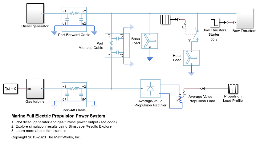
Marine Full Electric Propulsion Power System
A representative marine half-ship electrical power system with base load, hotel load, bow thrusters and electric propulsion.
Mars Helicopter System-Level Design
Use Simscape™ Electrical™ to model a helicopter with coaxial rotors suitable to fly on Mars. This helicopter takes inspiration from Ingenuity, the robotic helicopter developed by NASA, which accomplished the first powered flight on another planet.
Model Electric and Hybrid Electric Aircraft
Evaluate architectures of electric and hybrid electric aircraft against design criteria like flight range and maximum flight time. You can modify many aspects of the design, including the battery size and payload. Electric aircraft is an active area of development in the aerospace industry. You can then select the power network architectures and size the components, based on the results of your analysis. You can also reduce the number of design iterations you need to meet system-level design requirements, by using parameter sweeps.
- Since R2023b
- Open Live Script
Model Electric VTOL Aircraft Battery Pack
Model an electric vertical takeoff and landing (VTOL) aircraft and design the battery pack. You can download this model in MATLAB® or access it from MATLAB Central File Exchange and GitHub®.
- Since R2023b
- Open Live Script
Model Quadcopter Drone
Model a quadcopter that navigates a path to deliver a package. You can download this model in MATLAB® or access it from MATLAB Central File Exchange and GitHub®.
- Since R2023b
- Open Live Script
On-Board Charger for Two-Wheeler Electric Vehicle
Model an on-board charger for a two-wheeler vehicle by using an AC-DC converter and a DC-DC converter to achieve unity power factor (UPF) operation and constant current (CC) battery charging.
Power Split Hybrid Vehicle Electrical Network
The basic architecture of a power-split hybrid transmission. The planetary gear, along with the motor and generator, acts like a variable ratio gear. In this test, the vehicle accelerates from 15 m/s to 20 m/s, and then decelerates back to 15 m/s. The power management strategy uses just electrical power to perform the maneuver.
System-Level Battery Electric Vehicle (BEV) Model
Design a battery electric vehicle using abstract models of vehicle components. This is a simple, fast running model that you can use to estimate vehicle-level parameters like electrical efficiency. You can download this model in MATLAB® or access it from MATLAB Central File Exchange and GitHub®.
- Since R2023b
- Open Live Script
MATLAB Command
You clicked a link that corresponds to this MATLAB command:
Run the command by entering it in the MATLAB Command Window. Web browsers do not support MATLAB commands.
Seleziona un sito web
Seleziona un sito web per visualizzare contenuto tradotto dove disponibile e vedere eventi e offerte locali. In base alla tua area geografica, ti consigliamo di selezionare: .
Puoi anche selezionare un sito web dal seguente elenco:
Come ottenere le migliori prestazioni del sito
Per ottenere le migliori prestazioni del sito, seleziona il sito cinese (in cinese o in inglese). I siti MathWorks per gli altri paesi non sono ottimizzati per essere visitati dalla tua area geografica.
Americhe
- América Latina (Español)
- Canada (English)
- United States (English)
Europa
- Belgium (English)
- Denmark (English)
- Deutschland (Deutsch)
- España (Español)
- Finland (English)
- France (Français)
- Ireland (English)
- Italia (Italiano)
- Luxembourg (English)
- Netherlands (English)
- Norway (English)
- Österreich (Deutsch)
- Portugal (English)
- Sweden (English)
- Switzerland
- United Kingdom (English)


