Switched Reluctance Machine (Multi-Phase)
Four, five, or six-phase switched reluctance machine (SRM)
Libraries:
Simscape /
Electrical /
Electromechanical /
Reluctance & Stepper
Description
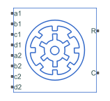
The Switched Reluctance Machine (Multi-Phase) block represents a four-phase, five-phase, or six-phase switched reluctance machine (SRM).
This diagram shows the motor construction for the four-phase machine.

This diagram shows the motor construction for the five-phase machine.

This diagram shows the motor construction for the six-phase machine.

Equations
The rotor stroke angle for a multiphase machine is
where:
θst is the stoke angle.
Ns is the number of phases.
Nr is the number of rotor poles.
The torque production capability, β, of one rotor pole is
The mathematical model for a switched reluctance machine (SRM) is highly nonlinear due to influence of the magnetic saturation on the flux linkage-to-angle curve, λ(θph). The phase voltage equation for an SRM is
where:
vph is the voltage per phase.
Rs is the stator resistance per phase.
iph is the current per phase.
λph is the flux linkage per phase.
θph is the angle per phase.
Rewriting the phase voltage equation in terms of partial derivatives yields this equation:
Transient inductance is defined as
or more simply as
Back electromotive force is defined as
Substituting these terms into the rewritten voltage equation yields this voltage equation:
Applying the co-energy formula to equations for torque,
and energy,
yields an integral equation that defines the instantaneous torque per phase, that is,
Integrating over the phases gives this equation, which defines the total instantaneous torque as
The equation for motion is
where:
J is the rotor inertia.
ω is the mechanical rotational speed.
T is the rotor torque. For the Switched Reluctance Machine block, torque flows from the machine case (block conserving port C) to the machine rotor (block conserving port R).
TL is the load torque.
J is the rotor inertia.
Bm is the rotor damping.
For high-fidelity modeling and control development, use empirical data and finite element calculation to determine the flux linkage curve in terms of current and angle, that is,
For low-fidelity modeling, you can also approximate the curve using analytical techniques. One such technique [2] uses this exponential function:
where:
λsat is the saturated flux linkage.
f(θr) is obtained by Fourier expansion.
For the Fourier expansion, use the first two even terms of this equation:
where a > b,
and
Calculating Iron Losses
The Switched Reluctance Machine (Multi-Phase) block implements the iron losses as a reduction in the electrical torque.
If you set the Stator parameterization parameter to
Specify parametric data, specify the
Magnetizing resistance parameter to model iron
losses.
If you set the Stator parameterization parameter to
Specify tabulated flux data, the block tabulates the
losses as the power lost in each stator phase. The losses for each stator only
depends on the stator current in that phase, the rotor angle (geometrically shifted
to that phase), and the rotor speed. The iron loss power of the rotor is computed as
a percentage of the total iron loss power, as specified in the Percentage
of total iron losses associated with the rotor parameter.
If you tabulate the losses with current, speed, and angle, the iron loss torque reduces the electrical torque of a generic "A" phase:
where is the torque loss computed as the mechanical power loss divided
by the rotor speed. wmin is the minimum
rotor speed and it is equal to 1
rad/s. This value prevents a division by zero when the
rotor speed is equal to 0.
If you tabulate the losses in function of only current and speed, the iron loss torque reduces the electrical torque of a generic "A" phase:
The iron losses are applied to the mechanical side as a reduction in torque. If you create the iron loss table, Ploss, from FEM results, the FEM tool might express the power lost as electrical power instead of mechanical power.
The total electrical torque is equal to the sum of the electrical torque of each phase:
The total power dissipated is equal to the sum of the iron losses and the copper losses:
If you expose the thermal ports of the block, the power dissipated in each phase act as heat sources in the motor and in the rotor:
The iron loss in the rotor is equal to a percentage of the total iron losses. This loss remains constant and does not depend on other states:
Then the remaining iron loss is distributed among the different stator phases:
Model Thermal Effects
You can expose thermal ports to model the effects of losses that convert power to heat. To expose the thermal ports, set the Modeling option parameter to either:
No thermal port— The block does not contain thermal ports.Show thermal port— The block contains multiple thermal conserving ports.
For more information about using thermal ports in actuator blocks, see Simulating Thermal Effects in Rotational and Translational Actuators.
Assumptions
A zero rotor angle corresponds to a rotor pole that is aligned perfectly with the a-phase, that is, peak flux.
Variables
To set the priority and initial target values for the block variables before simulation, use the Initial Targets section in the block dialog box or Property Inspector. For more information, see Set Priority and Initial Target for Block Variables.
Nominal values provide a way to specify the expected magnitude of a variable in a model. Using system scaling based on nominal values increases the simulation robustness. You can specify nominal values using different sources, including the Nominal Values section in the block dialog box or Property Inspector. For more information, see System Scaling by Nominal Values.
Examples

Four-Phase Switched Reluctance Machine Control
Control the rotor speed in a four-phase switched reluctance machine (SRM) based electrical drive. A DC voltage source feeds the SRM through a controlled four-arm bridge. The converter turn-on and turn-off angles are held constant.

Five-Phase Switched Reluctance Machine Control
Control the rotor speed in a five-phase switched reluctance machine (SRM) based electrical drive. A DC voltage source feeds the SRM through a controlled five-arm bridge. The converter turn-on and turn-off angles are held constant.

Six-Phase Switched Reluctance Machine Control
Control the rotor speed in an electrical drive based on a six-phase switched reluctance machine (SRM). A DC voltage source feeds the SRM through a controlled six-arm bridge. The converter turn-on and turn-off angles are constant.

Switched Reluctance Motor Parameterized with FEM Data
Build a model of a Switched Reluctance Motor (SRM). A custom Simscape™ composite component is used to construct the three stator pole pairs using the Simscape Electrical™ FEM-Parameterized Rotary Actuator as a base component. The states of the input pins (reverse, on/off) control the torque applied to the motor shaft.
Ports
Conserving
Parameters
References
[1] Boldea, I. and S. A. Nasar. Electric Drives. 2nd Ed. New York: CRC Press, 2005.
[2] Ilić-Spong, M., R. Marino, S. Peresada, and D. Taylor. “Feedback linearizing control of switched reluctance motors.” IEEE Transactions on Automatic Control. Vol. 32, Number 5, 1987, pp. 371–379.
Extended Capabilities
Version History
Introduced in R2018b