Configure AUTOSAR Queued Sender-Receiver Communication
In AUTOSAR queued sender-receiver (S-R) communication, AUTOSAR software components read and write data to other components or services. Data sent by an AUTOSAR sender software component is added to a queue provided by the AUTOSAR Runtime Environment (RTE). Newly received data does not overwrite existing unread data. Later, a receiver software component reads the data from the queue.
To implement queued S-R communication, AUTOSAR software components define:
An AUTOSAR sender-receiver interface with data elements.
AUTOSAR provide and require ports that send and receive queued data.
In Simulink®, you can:
Create AUTOSAR queued S-R interfaces and ports by using the AUTOSAR Dictionary, or if using a Simulink data dictionary, using the Architectural Data Editor.
Model AUTOSAR provide and require ports by using Simulink root-level outports and inports.
Map the outports and inports to AUTOSAR provide and require ports by using the Code Mappings editor. Set the AUTOSAR data access modes to
QueuedExplicitSendorQueuedExplicitReceive.Note
If you are using a Simulink data dictionary to store interfaces, you must configure these interfaces using either the Architectural Data Editor or the relevant programmatic interfaces,
Simulink.dictionary.ArchitecturalData.
To model sending and receiving AUTOSAR data using a queue, use Simulink Send and Receive blocks. If your queued S-R communication implementation involves states or requires decision logic, use Stateflow® charts. You can handle errors that occur when the queue is empty or full. You can specify the size of the queue. For more information, see Simulink Messages Overview.
You can simulate AUTOSAR queued sender-receiver (S-R) communication between component models, for example, in a composition-level simulation. Data senders and receivers can run at different rates. Multiple data senders can communicate with a single data receiver.
To get started, you can import components with queued S-R interfaces and ports from ARXML files into Simulink, or use Simulink to create the interfaces and ports.
Simulink Workflow for Modeling AUTOSAR Queued Send and Receive
This procedure outlines the general workflow for modeling AUTOSAR queued sender and receiver components in Simulink. This example assumes that a Simulink data dictionary is not used to store interfaces.
If you are using a Simulink data dictionary to store interfaces, you must configure these interfaces
using either the Architectural Data
Editor or the relevant programmatic interfaces, Simulink.dictionary.ArchitecturalData.
Configure one or more models as AUTOSAR queued sender components, and one model as an AUTOSAR queued receiver component. For each component model, use the AUTOSAR Dictionary and the Code Mappings editor to:
Create an S-R data interface and its data elements.
Create a sender or receiver port.
Map the sender or receiver port to a Simulink outport for sending or inport for receiving. Set the AUTOSAR data access mode to
QueuedExplicitSendorQueuedExplicitReceive.
For example, see Configure AUTOSAR Sender and Receiver Components for Queued Communication.
To implement AUTOSAR queued sender or receiver component behavior, use Simulink Send and Receive blocks. For more information, see Simulink Messages Overview.
If your queued S-R communication implementation involves states or requires decision logic, use Stateflow charts.
For more information, see Implement AUTOSAR Queued Send and Receive Messaging.
When you build an AUTOSAR queued sender or receiver component model:
Generated C code contains calls to AUTOSAR
Rte_Send_<port>_<DataElement>orRte_Receive_<port>_<DataElement>APIs.The generated code handles the status of the message receive calls.
Handling of message send status (such as queue overflow) can only be modeled in Stateflow. The generated code handles message send status only if a queued sender component implements the Stateflow logic.
Exported ARXML files contain descriptions for queued sender-receiver communication. The generated
ComSpecfor a queued port includes the port type and the queue length (based on Simulink message propertyQueueCapacity). In theSwDataDefPropsgenerated for the queued port data element,SwImplPolicyis set toQueued.
To simulate AUTOSAR queued sender-receiver communication in Simulink, create a containing composition, system, or harness model. Include the queued sender and receiver components as referenced models.
To provide queuing logic between sender and receiver components, you can insert a Simulink Queue block or Stateflow logic. With a Queue block, you can simulate a queue with a specific capacity. If you connect sender and receiver components directly, Simulink inserts a default queue with capacity 1.
For an example of connecting components directly, see the 1-to-1 composition model used in Configure Simulation of AUTOSAR Queued Sender-Receiver Communication.
For examples of inserting a Queue block or Stateflow logic between sender and receiver components, see Simulate N-to-1 AUTOSAR Queued Sender-Receiver Communication and Simulate Event-Driven AUTOSAR Queued Sender-Receiver Communication.
Configure AUTOSAR Sender and Receiver Components for Queued Communication
This example configures AUTOSAR queued sender and receiver components in Simulink. To see these models connected for simulation, see Configure Simulation of AUTOSAR Queued Sender-Receiver Communication.
openExample('mAutosarSlSenderSWC1')
openExample('mAutosarSlReceiverSWC')
Open an AUTOSAR model that you want to configure as a queued sender or receiver component. To create an S-R data interface and a queued sender or receiver port:
Open the AUTOSAR Dictionary.
Select S-R Interfaces. To create an S-R data interface, click the Add button
 . Specify its name and the number of
associated S-R data elements. This example uses one data element in both the
sender and receiver components.
. Specify its name and the number of
associated S-R data elements. This example uses one data element in both the
sender and receiver components.Select and expand the new S-R interface. Select DataElements and modify the data element attributes. This figure shows data element
DE1for the sender component.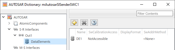
Expand the AtomicComponents node and select an AUTOSAR component. Expand the component.
Select the SenderPorts or ReceiverPorts view and use it to add the sender or receiver port you require. For each S-R port, select the S-R interface you created. For the sender component, this figure shows sender port
MsgOut, which uses S-R interfaceOut1.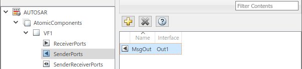
Open the Code Mappings editor. Select the Inports or Outports tab and use it to map a Simulink inport or outport to an AUTOSAR queued S-R port. For each inport or outport, select an AUTOSAR port, data element, and data access mode. Set the AUTOSAR data access mode to
QueuedExplicitSendorQueuedExplicitReceive. In the sender component, this figure shows Simulink outportMsgOut, which is mapped to AUTOSAR sender portMsgOutand data elementDE1, with data access modeQueuedExplicitSend.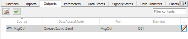
Note
Inports with data access mode
ErrorStatuscan not be mapped to inports with data access modeQueuedExplicitReceive.When you map an inport to an AUTOSAR queued receiver port, you can use either the Code Mappings or AUTOSAR Dictionary view of the port to modify its AUTOSAR communication specification (ComSpec) attribute
QueueLength. Select the inport in Code Mappings and either click the icon or open the AUTOSAR Dictionary. For more
information, see Configure AUTOSAR Sender-Receiver Port Communication Specification Attributes.
icon or open the AUTOSAR Dictionary. For more
information, see Configure AUTOSAR Sender-Receiver Port Communication Specification Attributes.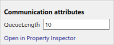
When you build an AUTOSAR queued sender or receiver component model:
Generated C code contains calls to AUTOSAR
Rte_Send_<port>_<DataElement>orRte_Receive_<port>_<DataElement>APIs. The generated code handles the status of the message send and receive calls.Exported ARXML files contain descriptions for queued sender-receiver communication. The generated
ComSpecfor a queued port includes the port type and the queue length (based on Simulink message propertyQueueCapacity). In theSwDataDefPropsgenerated for the queued port data element,SwImplPolicyis set toQueued.
To implement the messaging behavior of an AUTOSAR queued sender or receiver component, use Simulink or Stateflow messages. See Implement AUTOSAR Queued Send and Receive Messaging or Implement AUTOSAR Queued Send and Receive By Using Stateflow Messaging.
Implement AUTOSAR Queued Send and Receive Messaging
To model AUTOSAR queued sender and receiver component behavior, this example uses:
Simulink message blocks to implement messaging.
Stateflow charts to implement decision logic.
This example explains the construction of the example models
mAutosarSlSenderSWC1.slx and
mAutosarSlReceiverSWC.slx. These models can be accessed by
running the following code at the MATLAB® command line.
openExample('mAutosarSlSenderSWC1')
openExample('mAutosarSlReceiverSWC')
Other examples deploy the same sender and receiver models in 1-to-1 and N-to-1 messaging configurations. See Configure Simulation of AUTOSAR Queued Sender-Receiver Communication and Simulate N-to-1 AUTOSAR Queued Sender-Receiver Communication.
This figure shows the top level of AUTOSAR queued sender component
mAutosarSlSenderSWC1. The model contains:
Stateflow chart
Turn Signal Generator.A Simulink message Send block, wrapped in an enabled subsystem.
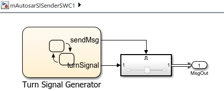
The chart has turn-signal and message-control outputs, which are connected to the
enabled subsystem. When the message-control signal becomes a positive value, the
subsystem is enabled. Inside the subsystem, the message Send block reads
the turn-signal data value, and sends a message containing the value to root outport
MsgOut.
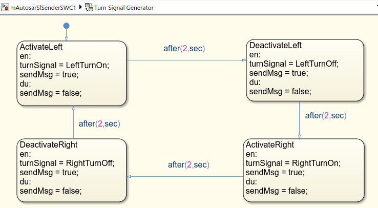
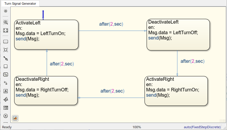
This figure shows the logic implemented in the Turn Signal
Generator chart. The chart has four states –
ActivateLeft, DeactivateLeft,
ActivateRight, and DeactivateRight. Each state
contains entry actions that assign a turn-signal data value and set the message-control
value to true. (See Communicate with Stateflow Charts by Sending Messages (Stateflow).) Periodic timing drives the message
output.
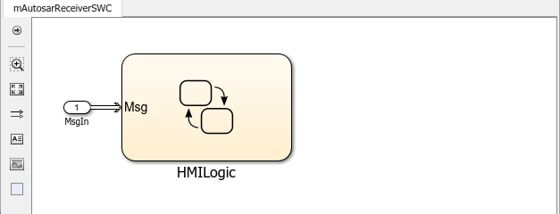
This figure shows the top level of AUTOSAR queued receiver component
mAutosarSlReceiverSWC. The model contains:
A Simulink message Receive block.
Stateflow chart
HMILogic.
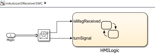
The root inport MsgIn provides a message to the
Receive block, which extracts the turn-signal data value from the
message. The block then outputs message-received and turn-signal data values to the
Stateflow chart.
The Receive block parameters are set to their Simulink defaults. For example, Show receive status is
selected, Use internal queue is cleared, and Value source
when queue is empty is set to Hold last
value.
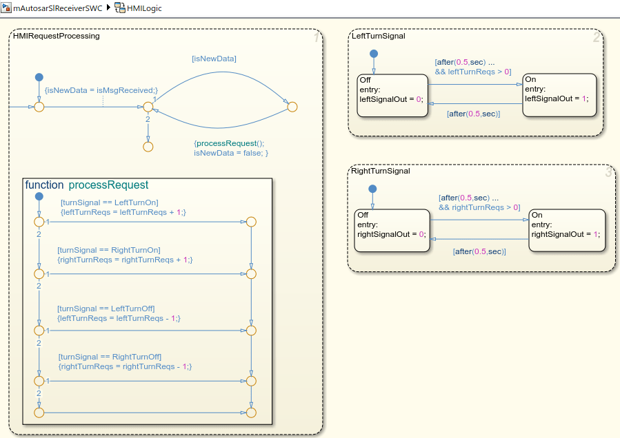
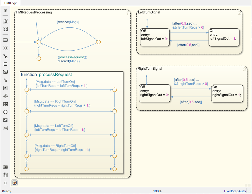
This figure shows the logic implemented in the HMILogic chart.
HMILogic contains states HMIRequestProcessing,
LeftTurnSignal, and RightTurnSignal.
HMIRequestProcessingreceives the message-received and turn-signal data inputs, sets anisNewDataflag, calls a function to process the turn-signal data, and then clears theisNewDataflag. TheprocessRequestfunction tests the received turn-signal data for values potentially set by the message sender --LeftTurnOn,RightTurnOn,LeftTurnOff, orRightTurnOff. Based on the value received, the function increments or decrements a request counter variable, eitherleftTurnReqsorrightTurnReqs. Periodic timing drives the message input.LeftTurnSignalandRightTurnSignaleach contain statesOffandOn. They transition fromOfftoOnbased on the value of request counterleftTurnReqsorrightTurnReqsand a time interval. When the request counter is greater than zero, the charts set a variable, eitherleftSignalOutorrightSignalOut, to 1. After a time interval, they transition back to theOffstate and setleftSignalOutorrightSignalOutto 0.
For sample implementations of multiple queued sender components in an N-to-1 messaging configuration, see the example models used in Simulate N-to-1 AUTOSAR Queued Sender-Receiver Communication.
For sample implementations of event-driven queued messaging, see the example models used in Simulate Event-Driven AUTOSAR Queued Sender-Receiver Communication.
Configure Simulation of AUTOSAR Queued Sender-Receiver Communication
To simulate AUTOSAR queued sender-receiver communication in Simulink®, create a containing composition, system, or harness model. Include the queued sender and receiver components as referenced models.
If you have one sender component and one receiver component, you potentially can connect the models directly. This example directly connects sender and receiver component models.
If you are simulating N-to-1 or event-driven messaging, you provide additional logic between sender and receiver component models. For example, see Simulate N-to-1 AUTOSAR Queued Sender-Receiver Communication and Simulate Event-Driven AUTOSAR Queued Sender-Receiver Communication.
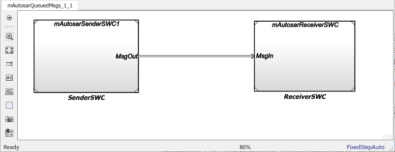
This example shows a composition-level model that contains queued sender and receiver component models and implements 1-to-1 communication. Periodic timing drives the messaging. The example uses the following three models which can be opened by running the code below:
open_system('mAutosarSlQueuedMsgs_1_1.slx') %(top model)
open_system('mAutosarSlSenderSWC1.slx')
open_system('mAutosarSlReceiverSWC.slx')
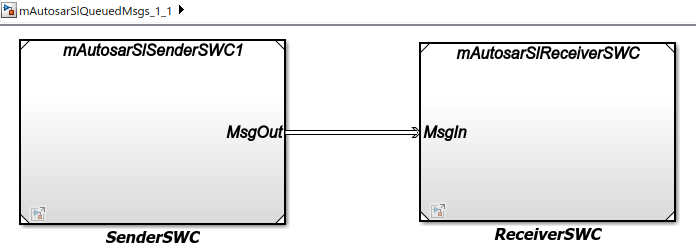
Models mAutosarSlSenderSWC1 and mAutosarSlReceiverSWC are the same sender and receiver components configured in Configure AUTOSAR Sender and Receiver Components for Queued Communication and implemented in Implement AUTOSAR Queued Send and Receive Messaging. Composition-level model mAutosarSlQueuedMsgs_1_1 includes them as referenced models and connects sender component port MsgOut to receiver component port MsgIn.
The top model mAutosarSlQueuedMsgs_1_1 is for simulation only. You can generate AUTOSAR C code and ARXML files for the sender and receiver component models, but not for the containing composition-level model.
Similarly, you can run software-in-the-loop (SIL) simulation for the sender and receiver component models, but not for the composition-level model.
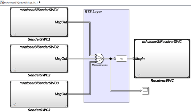
Simulate N-to-1 AUTOSAR Queued Sender-Receiver Communication
This example shows a composition-level model that contains three sender and one receiver component models, and implements N-to-1 communication. Periodic timing drives the messaging. The example extends the 1-to-1 example by adding two additional sender models and providing flow logic between the senders and receiver.
This example uses four models which can be accessed by running the following lines of code at the MATLAB® command line.
open_system('mAutosarSlQueuedMsgs_N_1.slx')
open_system('mAutosarSlSenderSWC1.slx')
open_system('mAutosarSlSenderSWC2.slx')
open_system('mAutosarSlSenderSWC3.slx')
open_system('mAutosarSlReceiverSWC.slx')
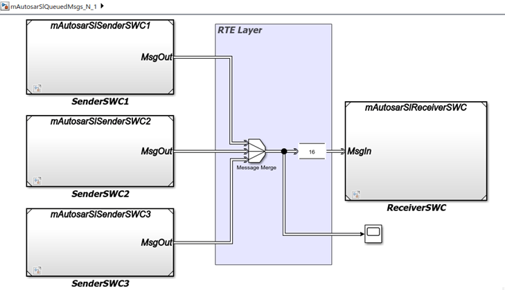
Composition-level model mAutosarSlQueuedMsgs_N_1 includes three sender components and a receiver component as referenced models. It connects the sender component MsgOut ports to intermediate MsgJoin processing logic, which in turn connects to a receiver component MsgIn port.
Models mAutosarSlSenderSWC1 and mAutosarSlReceiverSWC are the same sender and receiver components configured in Configure AUTOSAR Sender and Receiver Components for Queued Communication and implemented in Implement AUTOSAR Queued Send and Receive Messaging. The second and third sender components, mAutosarSlSenderSWC2 and mAutosarSlSenderSWC3, are similar to mAutosarSlSenderSWC1, but implement a second type of message input for the receiver to process.
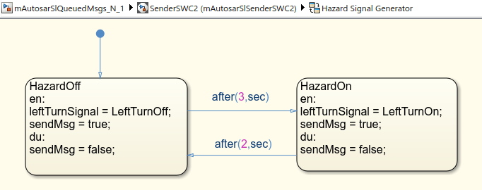
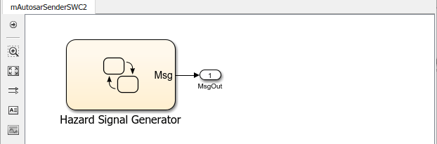
This figure shows the top level of AUTOSAR queued sender component mAutosarSlSenderSWC2. It contains Stateflow® chart Hazard Signal Generator, which provides logic for left-turn signals. The chart message-line output is connected to Simulink® root outport MsgOut. A corresponding Hazard Signal Generator chart to handle right-turn signals appears in sender component mAutosarSlSenderSWC3.
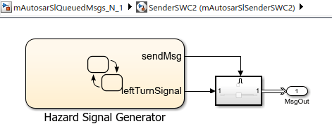
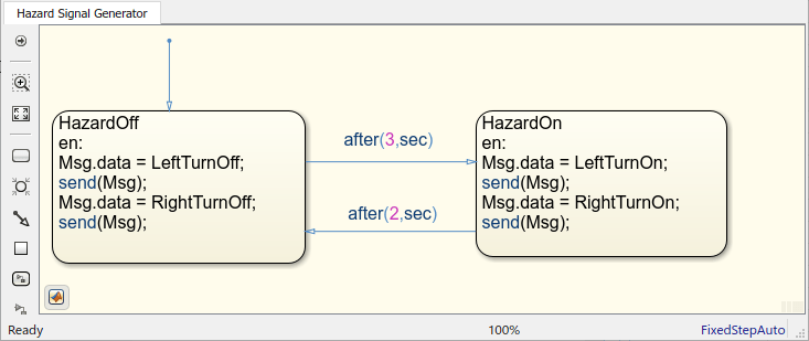
This figure shows the logic implemented in the Hazard Signal Generator chart. The chart has two states – HazardOff and HazardOn. Each state contains entry actions that assign values to message data and send messages. (See Communicate with Stateflow Charts by Sending Messages (Stateflow).) Periodic timing drives the message output.
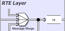
Between the sender and receiver components, a Message Merge block and a Queue block provide message merging and queuing.
The Message Merge block merges 3 message lines and outputs messages to the Queue block.
The Queue block stores messages from the 3 lines in a queue, based on the order of arrival.
The queue capacity is set to 16 messages.
When the queue is full and a message arrives, the block is set to overwrite the oldest message with the incoming message.
The message sorting policy is set to the policy AUTOSAR supports, first-in first-out (FIFO).
Each element at the head of the queue departs when the downstream ReceiverSWC block is ready to accept it. The top model mAutosarSlQueuedMsgs_N_1 is for simulation only. You can generate AUTOSAR C code and ARXML files for the referenced sender and receiver component models, but not for the containing composition-level model. Similarly, you can run software-in-the-loop (SIL) simulation for the sender and receiver component models, but not for the composition-level model.
Simulate Event-Driven AUTOSAR Queued Sender-Receiver Communication
This example shows a composition-level model in which a Simulink® function-call input event activates receiver component processing of a queued message. The example is implemented by using Stateflow® messages. For more Stateflow® messaging examples, see Implement AUTOSAR Queued Send and Receive By Using Stateflow Messaging.
This example using three models which can be accessed by running the following lines of code at the MATLAB® command line:
open_system('mAutosarDREventMsgs')
open_system('mAutosarMsgSender')
open_system('mAutosarHMILogicEvent')
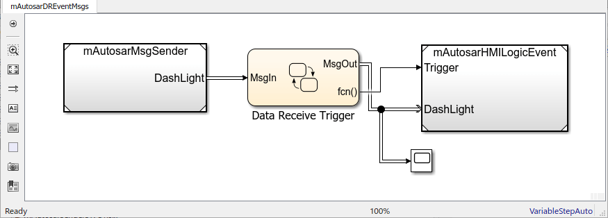
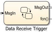
Composition-level model mAutosarDREEventMsgs includes a sender component and a receiver component as referenced models. It connects the sender message port DashLight to intermediate Data Receive Trigger logic, which in turn connects to receiver message port MsgIn and function trigger port Trigger.
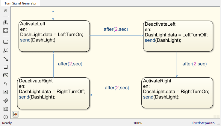
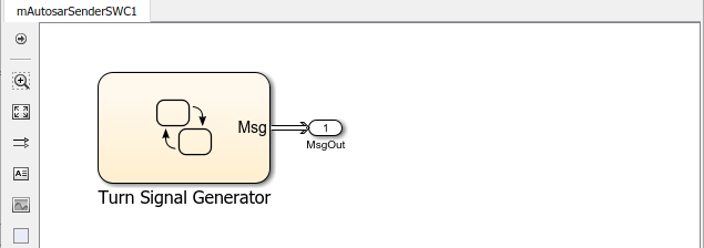
This figure shows the top level of AUTOSAR queued sender component mAutosarMsgSender, which contains Stateflow® chart Turn Signal Generator. The chart message-line output is connected to Simulink® root outport DashLight. (This sender component is similar to component mAutosarSenderSWC1 in the Stateflow® 1-to-1 and N-to-1 simulation examples in Implement AUTOSAR Queued Send and Receive By Using Stateflow Messaging.)
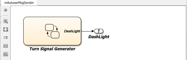
This figure shows the logic implemented in the Turn Signal Generator chart. The chart has four states – ActivateLeft, DeactivateLeft, ActivateRight, and DeactivateRight. Each state contains entry actions that assign a value to message data and send a message. (See Communicate with Stateflow Charts by Sending Messages (Stateflow).) Periodic timing drives the message output.
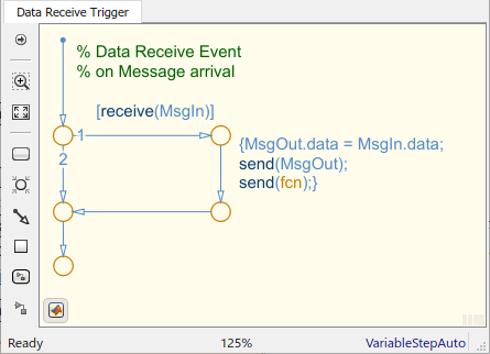
This figure shows the Data Receiver Trigger chart located between the sender and receiver components.
To receive a message, queued receiver logic uses receive(M):
If a valid message M exists,
receive(M)returns true.If a valid message does not exist, the chart removes a message from its associated queue, and
receive(M)returns true. Ifreceive(M)removes a message from the queue, the length of the queue drops by one.If message M is invalid, and another message could not be removed from the queue,
receive(M)returns false.
You can place receive on a transition (for example, [receive(M)]. Or, within a state, use an if condition (for example, if(receive(M))). For more information, see Communicate with Stateflow Charts by Sending Messages (Stateflow).
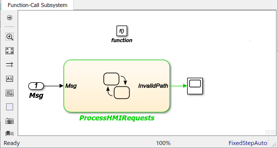
This figure shows the top level of AUTOSAR queued receiver component mAutosarHMILogicEvent, which contains a Simulink® function-call subsystem. The subsystem inports are a function-call trigger and message receiver port DashLight, which is configured for AUTOSAR data access mode QueuedExplicitReceive.
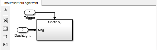
The function-call subsystem contains Stateflow® chart ProcessHMIRequests and a Trigger Port block. The chart message-line input is connected to Simulink® root inport Msg. A scope is configured to display the value of an InvalidPath variable. The Trigger Port block is configured for a function-call trigger and triggered sample time. Function-call input events sent from the Data Receiver Trigger chart in the top model activate the chart.
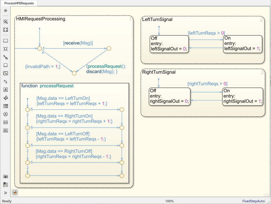
This figure shows the logic implemented in the ProcessHMIRequests chart. ProcessHMIRequests contains states HMIRequestProcessing, LeftTurnSignal, and RightTurnSignal. (This receiver chart is similar to chart HMILogic in the 1-to-1 and N-to-1 simulation examples.)
HMIRequestProcessingreceives a message from the message queue, calls a function to process the message, and then discards the message. TheprocessRequestfunction tests the received message data for values potentially set by the message sender --LeftTurnOn,RightTurnOn,LeftTurnOff, orRightTurnOff. Based on the value received, the function increments or decrements a request counter variable, eitherleftTurnReqsorrightTurnReqs. Function-call input events drive the message input. If the chart is incorrectly activated, theInvalidPathvariable is set to 1.LeftTurnSignalandRightTurnSignaleach contain statesOffandOn. They transition fromOfftoOnbased on the value of request counterleftTurnReqsorrightTurnReqs. When the request counter is greater than zero, the charts set a variable, eitherleftSignalOutorrightSignalOut, to 1. Then they transition back to theOffstate and setleftSignalOutorrightSignalOutto 0.
The top model mAutosarDREventMsgs is for simulation only. You can generate AUTOSAR C code and ARXML files for the referenced sender and receiver component models, but not for the containing composition-level model. Similarly, you can run software-in-the-loop (SIL) simulation for the sender and receiver component models, but not for the composition-level model.
Implement AUTOSAR Queued Send and Receive By Using Stateflow Messaging
Implement AUTOSAR Queued Send and Receive Messaging By Using Stateflow Messages
Configure Simulation of AUTOSAR Queued Sender-Receiver Communication
Simulate N-to-1 AUTOSAR Queued Sender-Receiver Communication
Implement AUTOSAR Queued Send and Receive Messaging By Using Stateflow Messages
To implement AUTOSAR queued sender or receiver component behavior, this example uses Stateflow messages. To create a Stateflow chart, follow the general procedure described in Model a Finite State Machine (Stateflow).
Add a chart to the AUTOSAR queued sender or receiver component model. Name the chart.
Open the chart and add message-related states.
For each state, add entry actions. Supported message keywords include:
send(M)-- Send message M.receive(M)-- Receive message M.isvalid(M)-- Check if message M is valid (popped and not discarded).discard(M)-- Explicitly discard message M. Messages are implicitly discarded on state exit after a message receive operation completes.
Add state transition lines and specify transition conditions or events on those lines.
Use conditions when you want to transition based on a conditional statement or a change of input value from a Simulink block. For more information, see Transition Between Operating Modes (Stateflow).
Use events when you want to transition based on a Simulink triggered or function-call input event. For more information, see Synchronize Model Components by Using Events (Stateflow).
Define data that stores state variables.
Connect the chart message-line inputs and outputs to Simulink root inports and outports.
For more information, see Messages (Stateflow).
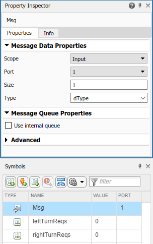
In the context of a Stateflow chart, you can modify message properties, such as data type and queue capacity. (For a list of properties, see Set Properties for a Message (Stateflow).) You can access message properties in the Property Inspector, a Message properties dialog box, or Model Explorer. To view or modify message properties with the Property Inspector:
Open a chart that uses messages.
In the Modeling tab, open Symbols Pane and Property Inspector.
In the Symbols view, select a message. The Property Inspector displays panes for Message Data Properties and Advanced properties.
If the chart is in a receiver component, the Property Inspector also displays Message Queue Properties. To configure the receiver component to use external AUTOSAR RTE message queues, make sure that property Use internal queue is cleared.
By default, message data type and queue capacity values are inherited from the
Stateflow message to which a Simulink root port is attached. Message data can use these Simulink parameter data types: int types,
uint types, floating-point types, boolean,
Enum, or Bus
(struct).
If you use imported bus or enumeration data types in Stateflow charts, typedefs are required for simulation. To generate typedefs automatically, select the Simulink configuration option Generate typedefs for imported bus and enumeration types. Otherwise, use Simulink configuration parameter Simulation Target > Custom Code > Header file to include header files with the definitions.
For sample implementations of queued sender and receiver components in a 1-to-1
configuration, see the example component models used in both Configure AUTOSAR Sender and Receiver Components for Queued Communication and Configure Simulation of AUTOSAR Queued Sender-Receiver Communication.
Models mAutosarSenderSWC1.slx and
mAutosarReceiverSWC.slx can be accessed by running the
following lines of code at the MATLAB command
line.
openExample('mAutosarSenderSWC1.slx')
openExample('mAutosarReceiverSWC.slx')
This figure shows the top level of AUTOSAR queued sender component
mAutosarSenderSWC1, which contains Stateflow chart Turn Signal Generator. The chart message-line
output is connected to Simulink root outport MsgOut.
This figure shows the logic implemented in the Turn Signal
Generator chart. The chart has four states –
ActivateLeft, DeactivateLeft,
ActivateRight, and DeactivateRight. Each
state contains entry actions that assign a value to message data and send a message.
(See Communicate with Stateflow Charts by Sending Messages (Stateflow).)
Periodic timing drives the message output.
This figure shows the top level of AUTOSAR queued receiver component
mAutosarReceiverSWC, which contains Stateflow chart HMILogic. The chart message-line input is
connected to Simulink root inport MsgIn.
To receive a message, queued receiver logic uses
receive(M):
If a valid message M exists,
receive(M)returns true.If a valid message does not exist, the chart removes a message from its associated queue, and
receive(M)returns true. Ifreceive(M)removes a message from the queue, the length of the queue drops by one.If message M is invalid, and another message could not be removed from the queue,
receive(M)returns false.
You can place receive on a transition (for example,
[receive(M)]. Or, within a state, use an
if condition (for example,
if(receive(M))). For more information, see Communicate with Stateflow Charts by Sending Messages (Stateflow).
This figure shows the logic implemented in the HMILogic chart.
HMILogic contains states
HMIRequestProcessing, LeftTurnSignal, and
RightTurnSignal.
HMIRequestProcessingreceives a message from the message queue, calls a function to process the message, and then discards the message. TheprocessRequestfunction tests the received message data for values potentially set by the message sender --LeftTurnOn,RightTurnOn,LeftTurnOff, orRightTurnOff. Based on the value received, the function increments or decrements a request counter variable, eitherleftTurnReqsorrightTurnReqs. Periodic timing drives the message input.LeftTurnSignalandRightTurnSignaleach contain statesOffandOn. They transition fromOfftoOnbased on the value of request counterleftTurnReqsorrightTurnReqsand a time interval. When the request counter is greater than zero, the charts set a variable, eitherleftSignalOutorrightSignalOut, to 1. After a time interval, they transition back to theOffstate and setleftSignalOutorrightSignalOutto 0.
For sample implementations of queued sender and receiver components in an N-to-1 configuration, see the example models used in Simulate N-to-1 AUTOSAR Queued Sender-Receiver Communication.
For sample implementations of event-driven queued messaging, see the example models used in Simulate Event-Driven AUTOSAR Queued Sender-Receiver Communication.
Configure Simulation of AUTOSAR Queued Sender-Receiver Communication
To simulate AUTOSAR queued sender-receiver communication in Simulink, create a containing composition, system, or harness model. Include the queued sender and receiver components as referenced models.
If you have one sender component and one receiver component, you potentially can connect the models directly. This example directly connects sender and receiver component models.
If you are simulating N-to-1 or event-driven messaging, you provide additional logic between sender and receiver component models. For example, see Simulate N-to-1 AUTOSAR Queued Sender-Receiver Communication and Simulate Event-Driven AUTOSAR Queued Sender-Receiver Communication.
This example shows a composition-level model that contains queued sender and receiver component models and implements 1-to-1 communication. Periodic timing drives the messaging. The example uses three models that can be accessed by running the following lines of code at the MATLAB command line.
openExample('mAutosarQueuedMsgs_1_1.slx')
openExample('mAutosarSenderSWC1.slx')
openExample('mAutosarReceiverSWC.slx')
Models mAutosarSenderSWC1 and
mAutosarReceiverSWC are the same sender and receiver
components configured in Configure AUTOSAR Sender and Receiver Components for Queued Communication and implemented in Implement AUTOSAR Queued Send and Receive Messaging. Composition-level
model mAutosarQueuedMsgs_1_1 includes them as referenced models
and connects sender component port MsgOut to receiver component
port MsgIn.
The top model mAutosarQueuedMsgs_1_1 is for simulation only.
You can generate AUTOSAR C code and ARXML files for the sender and receiver
component models, but not for the containing composition-level model.
Similarly, you can run software-in-the-loop (SIL) simulation for the sender and receiver component models, but not for the composition-level model.
Simulate N-to-1 AUTOSAR Queued Sender-Receiver Communication
This example shows a composition-level model that contains two sender and one receiver component models, and implements N-to-1 communication. Periodic timing drives the messaging. The example extends the 1-to-1 example by adding a second sender model and providing flow logic between the senders and receiver.
This example uses four models that can be accessed by running the following lines of code at the MATLAB command line.
openExample('mAutosarQueuedMsgs_N_1.slx') %top model
openExample('mAutosarSenderSWC1.slx')
openExample('mAutosarSenderSWC2.slx')
openExample('mAutosarReceiverSWC.slx')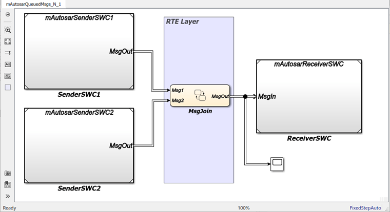
Composition-level model mAutosarQueuedMsgs_N_1 includes two
sender components and a receiver component as referenced models. It connects the
sender component MsgOut ports to intermediate
MsgJoin processing logic, which in turn connects to a
receiver component MsgIn port.
Models mAutosarSenderSWC1 and
mAutosarReceiverSWC are the same sender and receiver
components configured in Configure AUTOSAR Sender and Receiver Components for Queued Communication and implemented in Implement AUTOSAR Queued Send and Receive Messaging. The second sender
component, mAutosarSenderSWC2, is similar to
mAutosarSenderSWC1, but implements a second type of message
input for the receiver to process.
This figure shows the top level of AUTOSAR queued sender component
mAutosarSenderSWC2, which contains Stateflow chart Hazard Signal Generator. The chart
message-line output is connected to Simulink root outport MsgOut.
This figure shows the logic implemented in the Hazard Signal
Generator chart. The chart has two states –
HazardOff and HazardOn. Each state
contains entry actions that assign values to message data and send messages. (See
Communicate with Stateflow Charts by Sending Messages (Stateflow).)
Periodic timing drives the message output.
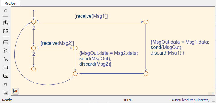
This figure shows the MsgJoin chart located between the sender
and receiver components.
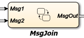
This figure shows the logic implemented in the MsgJoin chart.
The chart receives queued messages from both sender components and outputs them, one
at a time, to the receiver component. Messages from the first sender component,
mAutosarSenderSWC1.slx, are processed first. For each message
received, the chart copies the received message data to the outbound message, sends
the data, and discards the received message. (See Communicate with Stateflow Charts by Sending Messages (Stateflow).)
The top model mAutosarQueuedMsgs_N_1 is for simulation only.
You can generate AUTOSAR C code and ARXML files for the referenced sender and
receiver component models, but not for the containing composition-level
model.
Similarly, you can run software-in-the-loop (SIL) simulation for the sender and receiver component models, but not for the composition-level model.
Determine When a Queue Overflows
To check whether a message is lost because it was sent to a queue that was already
full, use the Stateflow
overflowed
operator:
overflowed(message_name)
overflowed operator, set the model to an
autosar.tlc target for both simulation and code generation
and verify that the inport or outport message connects to an external queue. In each
time step, the value of this operator is set when a chart adds a message to, or
removes a message from, a queue. It is invalid to use the
overflowed operator before sending or retrieving a message in
the same time step or to check the overflow status of a local message queue.By default, when a message queue overflows, simulation stops with an error. To
prevent a run-time error and allow the overflowed operator to
dynamically react to dropped messages, set the value of the Queue Overflow
Diagnostic property to Warning or
None. For more information, see Queue Overflow Diagnostic (Stateflow).
Check for Input Message Overflow. To check the overflow status of an input message queue, first remove a message from the queue. You can:
Guard a transition with the message and the
overflowedoperator.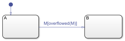
Guard a transition with the message and call the
overflowedoperator in the entry action of the destination state.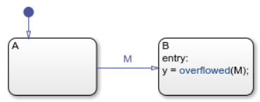
Guard a state
onaction with the message and call theoverflowedoperator in the action.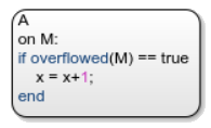
In a state action, use the
receiveoperator followed by theoverflowedoperator.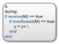
Calling the overflowed operator before
retrieving an input message in the same time step results in a run-time
error.
Check for Output Message Overflow. To check the overflow status of an output message queue, first add a message to the queue. You can:
Use the
sendoperator followed by theoverflowedoperator.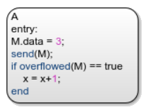
Use the
forwardoperator followed by theoverflowedoperator.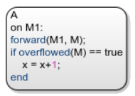
Calling the overflowed operator before sending
or forwarding an output message in the same time step results in a run-time
error.