Dyadic Synthesis Filter Bank
Reconstruct signals from subbands with smaller bandwidths and slower sample rates or compute inverse discrete wavelet transform (IDWT)
Libraries:
DSP System Toolbox /
Filtering /
Multirate Filters
Description
You can configure this block to compute the inverse discrete wavelet transform (IDWT) or reconstruct a signal from subbands with smaller bandwidths and slower sample rates. When the block computes the inverse discrete wavelet transform (IDWT) of the input, the output has the same dimensions as the input. Each column of the output is the IDWT of the corresponding input column. When reconstructing a signal, the block uses a series of highpass and lowpass FIR filters to reconstruct the signal from the input subbands, as illustrated in Multilevel Filter Banks (the Asymmetric one). The reconstructed signal has a wider bandwidth and faster sample rate than the input subbands.
You can specify the filter bank highpass and lowpass filters by providing vectors of filter coefficients. You can do so directly on the block dialog box. If you have a Wavelet Toolbox™ license, you can specify wavelet-based filters by selecting a wavelet from the Filter parameter. You must set the filter bank structure to asymmetric or symmetric, and specify the number of levels in the filter bank.
Note
To use a dyadic synthesis filter bank to perfectly reconstruct the output of a dyadic analysis filter bank, the number of levels and tree structures of both filter banks must be the same. In addition, the filters in the synthesis filter bank must be designed to perfectly reconstruct the outputs of the analysis filter bank. Otherwise, the reconstruction is not perfect. For an example that shows perfect reconstruction, see Wavelet Reconstruction and Noise Reduction.
This block automatically computes wavelet-based perfect reconstruction filters when the wavelet selection in the Filter parameter of this block is the same as the Filter parameter setting of the corresponding Dyadic Analysis Filter Bank block. The use of wavelets requires a Wavelet Toolbox license. To learn how to design your own perfect reconstruction filters, see References.
Examples
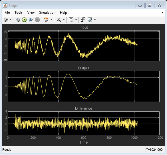
Wavelet Reconstruction and Noise Reduction
Uses the Dyadic Analysis Filter Bank and Dyadic Synthesis Filter Bank blocks to show both the perfect reconstruction property of wavelets and an application for noise reduction.
Ports
Input
Specify the data input as a column vector or a matrix.
The input characteristics vary depending on the block parameter settings as summarized here:
Number of levels parameter set to n
Tree structure parameter setting:
Asymmetric— Block accepts n+1 input subbandsSymmetric— Block accepts 2n input subbandsInput parameter setting can be
Multiple portsorSingle port.The inputs to this block are usually the outputs of a Dyadic Analysis Filter Bank block. Since the Dyadic Analysis Filter Bank block can output from either a single port or multiple ports, the Dyadic Synthesis Filter Bank block accepts inputs to either a single port or to multiple ports.
When you set the Input parameter to
Multiple ports, you must provide each subband to the block through a different input port as a vector or matrix. You should input the highest frequency band through the topmost port. When you set the Input parameter toSingle port, the block input must be a vector or matrix of concatenated subbands.
Note
Any output of a Dyadic Analysis Filter Bank block
whose parameter settings match the corresponding settings of this
block is a valid input to this block. For example, the setting of
the Dyadic Analysis Filter Bank block parameter
Output must be the same as the
Input parameter (Single
port or Multiple ports)
in this block.
Valid Inputs for Input Set to Single Port
Input must be a vector or matrix of concatenated subbands.
Each input column contains the subbands for an independent signal.
Upper input rows contain the high-frequency subbands, and the lower rows contain the low-frequency subbands.
Valid Inputs for Input Set to Multiple Ports
Each subband must be provided as a vector or a matrix to separate block input ports.
The columns of each input contains a subband for an independent signal.
The input to the topmost input port is the subband containing the highest frequencies, and the input to the bottommost port is the subband containing the lowest frequencies.
This figure illustrates the difference between the two settings for a 3-level asymmetric dyadic synthesis filter bank.
Valid Inputs to a 3-Level Asymmetric Dyadic Synthesis Filter Bank

For general information about the filter banks, see Dyadic Synthesis Filter Banks.
Note
This block always performs frame-based processing, and its inputs must be of certain sizes. To use input subbands that do not fit the criteria of this block, use the Two-Channel Synthesis Subband Filter block. You can connect multiple copies of the Two-Channel Synthesis Subband Filter block to create a multilevel dyadic synthesis filter bank.
Data Types: single | double
Complex Number Support: Yes
Output
Parameters
Block Characteristics
Data Types |
|
Direct Feedthrough |
|
Multidimensional Signals |
|
Variable-Size Signals |
|
Zero-Crossing Detection |
|
References
[1] Fliege, N. J. Multirate Digital Signal Processing: Multirate Systems, Filter Banks, Wavelets. West Sussex, England: John Wiley & Sons, 1994.
[2] Strang, G. and T. Nguyen. Wavelets and Filter Banks. Wellesley, MA: Wellesley-Cambridge Press, 1996.
[3] Vaidyanathan, P. P. Multirate Systems and Filter Banks. Englewood Cliffs, NJ: Prentice Hall, 1993.
Extended Capabilities
Version History
Introduced before R2006a