Power Converter Control | How to Use Rapid Control Prototyping to Validate Electric Motors and Power Converters, Part 4
From the series: How to Use Rapid Control Prototyping to Validate Electric Motors and Power Converters
Learn how to test new controls, tune parameters, and log data for a DC-DC converter and a 3-phase grid-tied inverter. Rapid control prototyping (RCP) enables you to:
- Use a real-time target computer instead of the embedded processor
- Generate C and VHDL code from Simulink® models
- Configure I/O and communication protocols from Simulink
Published: 11 Nov 2021
Let us say that we want to design a digital controller for a DC-DC power converter that regulates the voltage to light the LEDs in a car headlamp. We use the SEPIC topology, where SEPIC stands for single-ended primary inductor converter. This is essentially a bus converter, followed by a bulk boost converter, and can increase or decrease source voltage as needed.
SEPIC converters typically require very high frequencies in the range of hundreds of kilohertz. We'll use rapid control prototyping, as we want to develop and test our control algorithm as fast as possible. We also want to adapt the control, tune the parameters, and measure data on the fly, from Simulink.
By using Simulink real-time and Speedgoat hardware, we'll aim at automatically generating C or HDL code, and configure all inputs and outputs from Simulink, with Speedgoat driver blocks. For rapid control prototyping, we'll use a baseline real-time target machine, with an IO397 Simulink-programmable FPGA I/O module from Speedgoat, as a Xilinx FPGA analog input and output channels, as well as configurable digital I/O lines.
In this case, we will be using the analog inputs and the PWM functionality to generate 100 kilohertz switching frequency. With this flexible platform, we can also use a PID Autotuner tuner blocks, from Simulink Control Design, for automated tuning.
And by the way, if our DC-DC converter was not ready, we could also use the switches in the power module from Speedgoat. And by the way, if our DC-DC converter was not ready, we could also emulate the converter dynamics using HEV develop of testing.
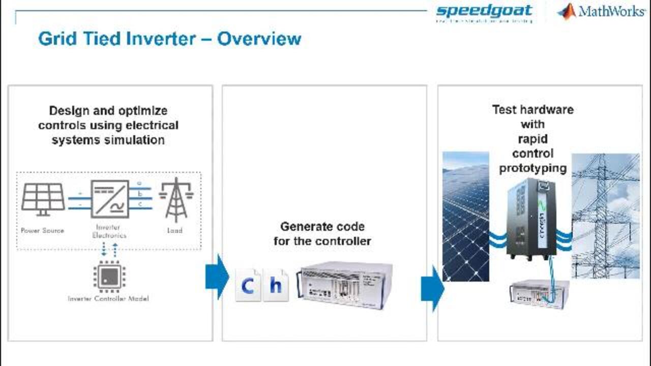
To develop a controller for a grid tied three-phase inverter, we'll start with desktop simulation, including the solar panel, the inverter, and the grid. Once we're happy with the desktop simulation, we generate C and HDL code automatically from Simulink. We can then test our controller for the greater inverter by connecting it to a Speedgoat target computer.
In this case, we'll use a Cinergia two-level, three-phase inverter with an LCL filter for prototyping the power electronics part. Developing a grid tied inverter is a complex task, that not only involves expensive hardware, it also could affect the grid and other of its users.
We can reset the development process with model-based design. We would start with desktop simulation, involving the plant and the controller. Then, rapid control prototyping provides a reliable test platform with proven I/O connectivity, and the capacity to measure and change parameters on the fly.
Once the embedded controller seems ready, it is still important to use hardware-in-the-loop testing to validate and thoroughly test under all operating conditions and full conditions. It is just then that we deploy using production code generation to an embedded platform.
We can learn more about this topic in a MATLAB expert talk on grid tied solar inverters. For doing rapid control prototyping for a grid tied inverter, we could use a performance real-time target machine, including a large amount of low-latency analog measurements.
In this case, we use Speedgoat analog I/O modules with DMA memory access to achieve the lowest latency with multiple measurements. We also use a configurable FPGA I/O module, including several FPGA gold modules, like PWM generators. We also have interrupts that are used to create a link between the PWM and the analog signals to make sure that we always measure currents when the transistor in series is properly closed. A measurement would not be valid otherwise.
Speedgoat interface from the Cinergia power converter includes connectors for Speedgoat cables to transfer both analog measurements from current and voltage, and also to provide access to the gate drivers via PWM switching, or similar.
The power converter interface also includes electrical protection features, like overcurrent protection, that provides an additional safety mechanism. For this sample, we used a 15 kilowatt two-level, three-phase power converter from Cinergia. But as Diego previously mentioned, they are compatible interfaces for projects requiring from a few hundred watts to around 160 kilowatts.

Featured Product
Simulink


Seleziona un sito web
Seleziona un sito web per visualizzare contenuto tradotto dove disponibile e vedere eventi e offerte locali. In base alla tua area geografica, ti consigliamo di selezionare: United States.
Puoi anche selezionare un sito web dal seguente elenco:
Americhe
- América Latina (Español)
- Canada (English)
- United States (English)
Europa
- Belgium (English)
- Denmark (English)
- Deutschland (Deutsch)
- España (Español)
- Finland (English)
- France (Français)
- Ireland (English)
- Italia (Italiano)
- Luxembourg (English)
- Netherlands (English)
- Norway (English)
- Österreich (Deutsch)
- Portugal (English)
- Sweden (English)
- Switzerland
- United Kingdom (English)