Implementing a PLCnext-Based Turbine Control System in Simulink
Jakoba Reimann, Sokratel GmbH
Model-Based Design provides an efficient approach to modeling and designing control systems. Both the controller and the plant model are implemented in MATLAB® and Simulink®. By linking these models, you can optimally analyze the controller and adapt it to the environment and the plant. Different stages of testing like unit tests or model-in-the-loop tests are optimally implemented with Simulink Test™. Further advantages like a visual representation of data flow, intuitive language learning, and smooth implementation of new features make Simulink the ideal choice for Sokratel’s task of implementing a PLCnext-based wind turbine control system. This talk focuses on the following topics:
- What is Model-Based Design and why does Sokratel use it?
- The iterative process of refining a requirement from the idea to the prototype
- Introduction to the process based on a small example
- Toolchain integration: How Sokratel automates daily work
- Testing concept: Hardware-in-the-loop testing with the PLCnext system
After this talk, you will have an idea of how to successfully lead your team on the road from MATLAB and Simulink development to the final product on hardware.
Published: 8 May 2023
[AUDIO LOGO]
Yes, welcome, everyone, to the presentation. I'll talk about the following topic, From Requirement to Execution, Implementing a PLCnext-Based Turbine Control System in Simulink. My name is Jakoba Reimann and I'm from the company Sokratel.
Let's first have a look at the key takeaways you'll get after the presentation. You'll understand the benefits and advantages of model-based design. Further, you'll understand how MATLAB Simulink can help all of us to get one step closer to a world with 100% renewable energies. And last but not least, I will show you the way from the first idea you have in mind to the final product on your hardware.
A short introduction to Sokratel, we are a company based in Germany with different departments over the country. We have the focus on software development. We have a field of firmware development, PLC automation over continuous integration, also model-based design. And model-based design is what we want to focus on today.
In model-based design, we have a team of about 20 developers. And we support our customer in the fields of control design and implementation, over code generation, and also the test concept creation and implementation. But let's dive deeper into the presentation and what we will talk about in the 20 minutes.
So I will first give you an overview of the theory behind model-based design and why we use it and what are the advantages. And then on the basis of an example requirement, I will show you the process from the idea you have in mind to the prototype. But what is model-based design?
So based on requirement specification you get, for example, from your customer, you design your controller and also a model of the plant. And the plant is a system you want to control. This could be anything. This could be a train or a car, or a wind turbine. And wind turbines are what we want to talk about here.
So after you've designed your controller with a model of the plant, you can use automatic code generation to deploy your code on your target hardware. The whole process, all the development steps, are continuously verified and tested to make sure that bugs are identified quite early in the process. MATLAB Simulink is the right tool for model-based design.
Here we have an example. We have a controller and closed loop with a plant model. So as I said, you create a model of the plant, the system you want to control, to verify your controller directly in closed loop. And you can then verify it and configure it ideally. You don't have to re-implement your controller model in a PLC-readable language, like structured text or C++ or any other language, but you can use automatic code generation to automatically generate code from your controller model. And this code is applicable for different target hardware and different end targets.
Since we continuously verify our model and the implementation process, we can quickly detect faults and can easily fix them. And the whole process, the whole development process, is able to be integrated in a pipeline in continuous integration, where you can automate your test executions and you can run a static model and code analysis and make sure that the model you've created is guideline-compliant.
So let's compare the traditional development approaches to the model-based design software approach. In a traditional development approach, you would use several tools throughout the development process. And as a developer, I have to get to know all those tools and the interfaces between them. To reduce inefficiencies, you can use model-based design with only one tool environment, which is Simulink and its toolboxes.
In the traditional development process, then after you've created your controller model, manually translate it into an executable code-- and manually means, yeah, a lot of time and it's quite error-prone. And therefore you use model-based design with automatic code generation to reduce the defects and time. And also in traditional development approaches, we would test after we finalized our implementation and to early discover bugs. In model-based design we test throughout the whole development process.
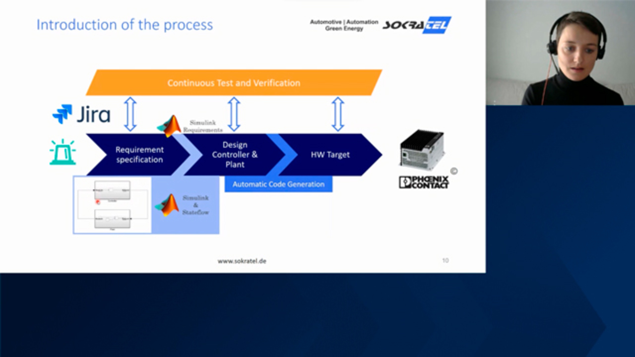
So you've got an overview of the theory now. So what is model-based design and what are the advantages of it? And I want to show you now an example requirement to show you how this process is implemented in detail. Here's the example requirement, which says during the night the turbine shall activate a green light on top of the nacelle.
So you can imagine, here's the green light. Here's the turbine. Here's a nacelle. And we want to activate the light, flash the light when it's night. We now have on our left-hand side of the model-based design process the idea we want to implement.
And on the right-hand side, we have the target hardware, the hardware which is in the end controlling the real turbine. This here is a PLCnext from Phoenix Contact we want to focus on in the talk. So the first step would be to write down your requirements in a tool like Jira and start to implement it in Simulink and Stateflow.
We implement our controller part and the controller model, the actuating of the light based on whether it's day or night. And the green light you would implement in the plan model. Imagine you have already implemented a whole turbine control system and just want to add this green light functionality. You can link your requirement you have in Jira with a Simulink requirements toolbox to the implementation in Simulink.
And after you've finished with your implementation, you can use another toolbox-- it's called Simulink test, to verify your implementation. We have different test steps here. The first one would be the unit test, which is an input-output test where we test the behavior of the model.
You put in the day time and you verify if a set point is set correctly. The next step would be that you test your model in closed loop with your plan. So this test step is called model in the loop. And we go into this in detail in the next slide.
After you've verified your model now, that it runs correctly and as intended, you can use the automatic code generation with the Simulink coder toolbox from Simulink and the PLCnext target for Simulink, which is an extension for the PLCnext. And then you can generate code automatically, which you can run on your target hardware. This step can also be tested via Simulink test. And we call this test step hardware in the loop.
Hardware in the loop is the test step we want to go into detail also. So but let's have a look into the model in the loop first. Here we test the closed loop behavior with a representative model of the plant. So we connect our controller model where we've added the actuating of the light and further implementation of other functionalities with our plan model, which is representing the turbine.
This is done purely simulative, so we are still simulating the controller and the plan model on our developer PCs. And we test different scenarios here. For example, is the wind turbine aligning to the wind if we change the wind direction? And the nacelle should always look into the wind, that it comes directly from the front side.
And we can make sure that our new implementation we've added is not causing any trouble in the implementation we've done before. So we integrate our new model part into a whole system. In the next step, the hardware in the loop, we now have real hardware. So we test our physical hardware, a PLC here, PLCnext from Phoenix, for example, with a representative model of the plant.
The plant model now is executed on a real-time target machine, for example, the PC from Speedgoat. And we don't test the functionality in detail anymore, as we've done with a MiL test, but we focus here on the communication between the different applications and their interaction. Since we haven't built a prototype with a green light on it, and we are still purely stimulative regarding the simulation of the turbine, it's really time and cost efficient.
When you want to test it, now you can use different interfaces. As a developer I can connect the PLC via OPC UA, to the PLC. And the real-time target machine I can connect via the XIL API with my developer PC and can then use different test schedulers like Exam, ECU Test, but also Simulink test, to run tests for this HiL setup.
The PLCnext engineer offers the possibility of the model viewer. Here you can see how the model looks like on the PLC. So we have here an example of a model with some inputs and outputs, and in between some subsystems, or enabled subsystems. This is how it looks in Simulink.
Then we generate code from it and put it on the hardware on our PLCnext and here you can see how it looks like on the PLCnext, and you can use this view for manual debugging, for example. So we've now seen several testing steps, the unit test as the first test step we have, where we just test the smallest functionality, then the model in the loop, the MiL testing, where we integrate our new controller model into a whole system and verify that everything works as intended. And then the last step, the hardware in the loop, where we have our real hardware, the real PLC which is in the end integrated in the real turbine, but still a simulation of the plant.
And that was a lot of test steps, and we can use some tools to automate those test steps. And I will show you here how we can do that. So as a developer, I can commit my changes of the Simulink model to get the implementation of the new controller functionality, which is actuating the light. I commit this model to a pipeline, Jenkins, Bamboo, or other pipelines, and then automatically several steps are executed.
We see it here. So the first steps, a step is the checkout. So the pipeline, Jenkins for example, checks out the model I've committed to get. In the next step, a static code analysis is executed with the help of the Simulink model advisor toolbox. Here we can verify that our model is implemented guideline compliant, that we, for example, put all of the inputs on the left-hand side, and all of the outputs on the right-hand side, or we didn't use any blocks which are blacklisted. All right, further rules you can imagine.
Then, on the next step, the test execution is performed, where all your tests you have specified and implemented are automatically executed, and the results are transmitted to Jira. The next step is the code generation where, from your model, you have committed the code which can run on the PLC is generated automatically. And the last step is the cleanup, that the pipeline is ready for the next commit.
And as a developer, I just have to have a look into the results of this pipeline, so I can check the results of the code analysis and can have a look if I have to change anything in my implementation. And I can have a look into the results of the test execution. And I don't have to take care of these steps manually.
So I gave you an overview now of model-based design. What is it, actually? And what is the theory behind it? Why do we use it, and how is the process from the idea you have to the prototype? And that was still some theory.
And that was still some theory. Now we want to go into the reality, and therefore with our customer Enercon, we realized a complete turbine control system. And based on model-based design, we now have the first turbines as prototypes running with Simulink. Thank you very much for your attention.
[AUDIO LOGO]
Related Products
Learn More
Featured Product
MATLAB
Up Next:


Related Videos:


Seleziona un sito web
Seleziona un sito web per visualizzare contenuto tradotto dove disponibile e vedere eventi e offerte locali. In base alla tua area geografica, ti consigliamo di selezionare: United States.
Puoi anche selezionare un sito web dal seguente elenco:
Americhe
- América Latina (Español)
- Canada (English)
- United States (English)
Europa
- Belgium (English)
- Denmark (English)
- Deutschland (Deutsch)
- España (Español)
- Finland (English)
- France (Français)
- Ireland (English)
- Italia (Italiano)
- Luxembourg (English)
- Netherlands (English)
- Norway (English)
- Österreich (Deutsch)
- Portugal (English)
- Sweden (English)
- Switzerland
- United Kingdom (English)