Main Content

conformalArray

Create conformal antenna array

Description

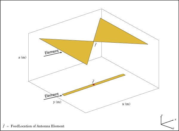
The conformalArray object creates an antenna array using any element from the antenna or array library. You can also specify an array of any arbitrary geometry, such as a circular array, a nonplanar array, an array with nonuniform geometry, or a conformal array of arrays.

Conformal arrays are used in:

  • Direction-finding systems that use circular arrays or stacked circular arrays.

  • Aircraft systems due to surface irregularities or mechanical stress.
Creation

Description

example

array = conformalArray creates a conformal antenna array using the default antenna element, shape, and antenna positions.

example

array = conformalArray(Name=Value) creates a conformal antenna array, with additional Properties specified by one or more name-value arguments. Name is the property name and Value is the corresponding value. You can specify several name-value arguments in any order as Name1=Value1,..., NameN=ValueN. Properties that you do not specify retain default values.

Properties

expand all

Position of the feed or origin for each antenna element, specified as an M-by-3 real matrix. M is the number of element positions. By default, M is 2. To specify additional antenna elements, add additional element positions in the conformal array.

Example: [0.1 0.1 0.1; -0.1 -0.1 -0.1; 0.2 0.2]

Data Types: double

Individual antenna or array elements or backing structure without exciter (cavity or reflector), specified as a 1-by-M cell array, where M is the number of positions defined by the ElementPosition property. By default, a conformal array has two elements, a dipole and a bowtie antenna. To specify additional elements, add more element positions to the conformal array. The antenna object can be an element from the Antenna Catalog, an installedAntenna object, a pcbStack object, or an antenna created using customAntennaGeometry, customAntennaMesh, customAntennaStl, or customAntenna objects. The array object can be an element from the Array Catalog except infinite array and egg crate array, or a customArrayMeshobject. You can add balanced and unbalanced antennas to the same conformal array. You can also add cavity and reflector backing structures without an exciter as elements of the conformal array.

A conformal array cannot have only backing structure as the element. Specify at least one antenna or array element in addition to the backing structure.

Note

Conformal arrays created using unbalanced antennas with infinite ground plane are currently unsupported.

Also, following antennas are unsupported as an element:

Example: conformalArray(Element={monopole monopole}) creates a conformal array consisting of two monopole antenna elements.

Example: conformalArray(Element={linearArray rectangularArray}) creates a conformal array consisting of a linear array and a rectangular array.

Example: ca =conformalArray;ca.Element={cavity(Exciter=[]) ca.Element{2}}; creates a conformal array of a cavity backing structure and a bowtie antenna element.

Data Types: cell

Position reference for the antenna element, specified as either "origin" or "feed". For more information, see Position Reference.

Example: "origin"

Data Types: string

Excitation amplitude of the antenna elements, specified as a scalar or a positive vector. To model dead elements, set the property value to 0.

Example: 3

Example: [3 0] creates a two-element conformal array with the excitation amplitudes of the two elements equal to 3 and 0 respectively.

Data Types: double

Phase shift for antenna elements, specified as a scalar or a real vector in degrees.

Example: [-45 -45 45 45]

Data Types: double

Tilt angle of the array in degrees, specified as a scalar or vector. For more information, see Rotate Antennas and Arrays.

Example: 90

Example: Tilt=[90 90],TiltAxis=[0 1 0;0 1 1] tilts the array at 90 degrees about the two axes, defined by the vectors.

Data Types: double

Tilt axis of the array, specified as one of these values:

  • Three-element vectors of Cartesian coordinates in meters. In this case, each vector starts at the origin and lies along the specified points on the x-, y-, and z-axes.

  • Two points in space, specified as a 2-by-3 matrix corresponding to two three-element vectors of Cartesian coordinates. In this case, the array rotates around the line joining the two points.

  • "x", "y", or "z" to describe a rotation about the x-, y-, or z-axis, respectively.

For more information, see Rotate Antennas and Arrays.

Example: [0 1 0]

Example: [0 0 0;0 1 0]

Example: "Z"

Data Types: double | string

Object Functions

showDisplay antenna, array structures, shapes, or platform
infoDisplay information about antenna or array
arrayFactorArray factor in dB
beamwidthBeamwidth of antenna
chargeCharge distribution on antenna or array surface
correlationCorrelation coefficient between two antennas in array
currentCurrent distribution on antenna or array surface
designDesign prototype antenna or arrays for resonance around specified frequency or create AI-based antenna from antenna catalog objects
efficiencyRadiation efficiency of antenna
doaDirection of arrival of signal
efficiencyRadiation efficiency of antenna
EHfieldsElectric and magnetic fields of antennas or embedded electric and magnetic fields of antenna element in arrays
impedanceInput impedance of antenna or scan impedance of array
layoutDisplay array or PCB stack layout
meshMesh properties of metal, dielectric antenna, or array structure
optimizeOptimize antenna or array using SADEA optimizer
patternPlot radiation pattern and phase of antenna or array or embedded pattern of antenna element in array
patternAzimuthAzimuth plane radiation pattern of antenna or array
patternElevationElevation plane radiation pattern of antenna or array
rcsCalculate and plot radar cross section (RCS) of platform, antenna, or array
returnLossReturn loss of antenna or scan return loss of array
sparametersCalculate S-parameters for antennas and antenna arrays
vswrVoltage standing wave ratio (VSWR) of antenna or array element

Examples

collapse all

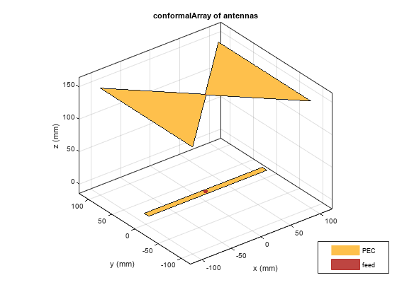
Create a default conformal array.

c = conformalArray
c = 
  conformalArray with properties:

            Element: {[1x1 dipole]  [1x1 bowtieTriangular]}
    ElementPosition: [2x3 double]
          Reference: 'feed'
     AmplitudeTaper: 1
         PhaseShift: 0
               Tilt: 0
           TiltAxis: [1 0 0]

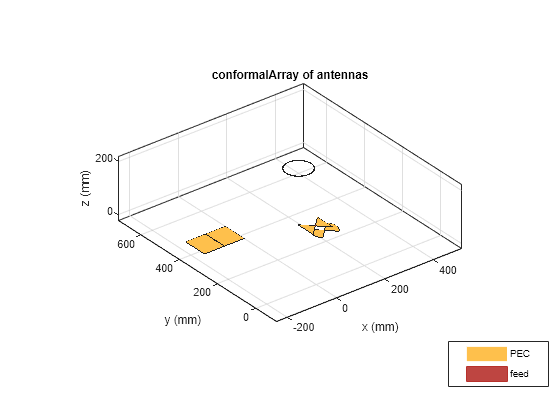
show(c)

Figure contains an axes object. The axes object with title conformalArray of antennas, xlabel x (mm), ylabel y (mm) contains 6 objects of type patch, surface. These objects represent PEC, feed.

Define the radius and the number of elements for the array.

r = 2;
N = 12;

Create an array of 12 dipoles.

elem = repmat(dipole(Length=1.5),1,N);

Define the x,y,z values for the element positions in the array.

del_th = 360/N;
th = del_th:del_th:360;
x = r.*cosd(th);
y = r.*sind(th);
z = ones(1,N);
pos = [x;y;z];

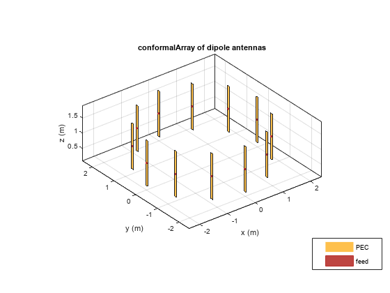
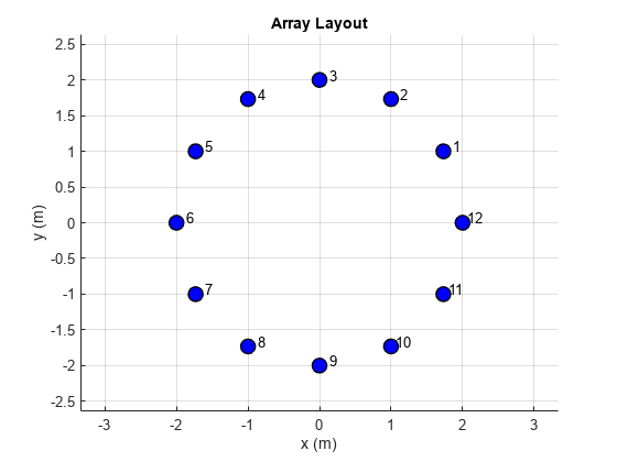
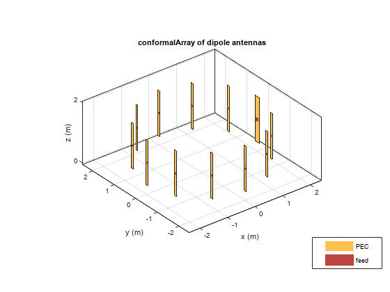
Create a circular array using the defined dipoles and then visualize it. Display the layout of the array.

c = conformalArray(Element=elem,ElementPosition=pos');
show(c)

Figure contains an axes object. The axes object with title conformalArray of dipole antennas, xlabel x (m), ylabel y (m) contains 36 objects of type patch, surface. These objects represent PEC, feed.

figure
layout(c)

Figure contains an axes object. The axes object with title Array layout, xlabel x (m), ylabel y (m) contains 13 objects of type scatter, text.

Change the width of the fourth and the twelfth element of the circular array. Visualize the new arrangement.

c.Element(4).Width = 0.05;
c.Element(12).Width = 0.2;
figure
show(c)

Figure contains an axes object. The axes object with title conformalArray of dipole antennas, xlabel x (m), ylabel y (m) contains 36 objects of type patch, surface. These objects represent PEC, feed.

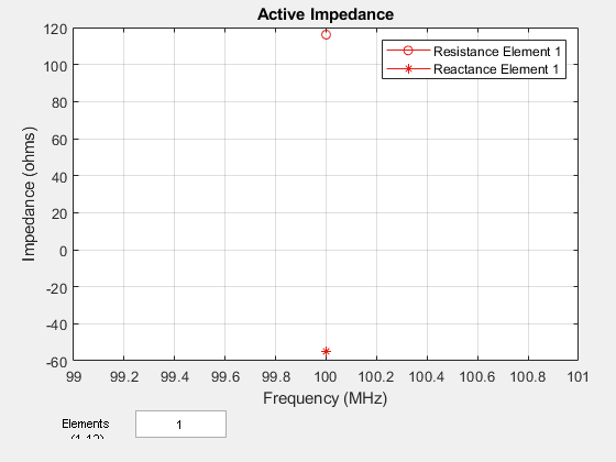
Calculate and plot the impedance of the circular array at 100 MHz. The plot shows the impedance of the first element in the array.

figure
impedance(c,100e6)

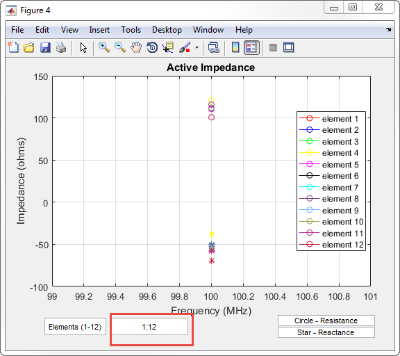
Figure contains an axes object and other objects of type uicontrol. The axes object with title Active Impedance, xlabel Frequency (MHz), ylabel Impedance (ohms) contains 2 objects of type line. These objects represent Resistance element 1, Reactance element 1.

To view the impedance of all the elements in the array change the value from 1 to 1:12 as shown in the figure.

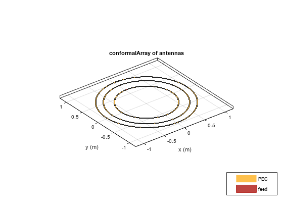
Define three circular loop antennas of radii 0.6366 m (default), 0.85 m, and 1 m, respectively.

l1 = loopCircular;
l2 = loopCircular(Radius=0.85);
l3 = loopCircular(Radius=1);

Create a concentric array that uses the origin of circular loop antennas as its position reference.

c = conformalArray(Element={l1 l2 l3},ElementPosition=[0 0 0; 0 0 0;...
     0 0 0],Reference="origin");
show(c)

Figure contains an axes object. The axes object with title conformalArray of antennas, xlabel x (m), ylabel y (m) contains 9 objects of type patch, surface. These objects represent PEC, feed.

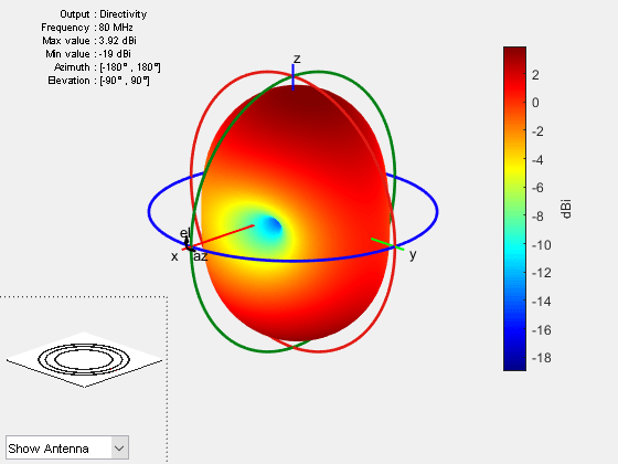
Visualize the radiation pattern of the array at 80 MHz.

pattern(c,80e6)

Figure contains an axes object and other objects of type uicontrol. The axes object contains 9 objects of type patch, surface.

Create a dipole antenna to use in the reflector and the conformal array.

d = dipole(Length=0.13,Width=5e-3,Tilt=90,TiltAxis='Y');

Create an infinite groundplane reflector antenna using the dipole as exciter.

rf = reflector(Exciter=d,Spacing=0.15/2,GroundPlaneLength=inf);

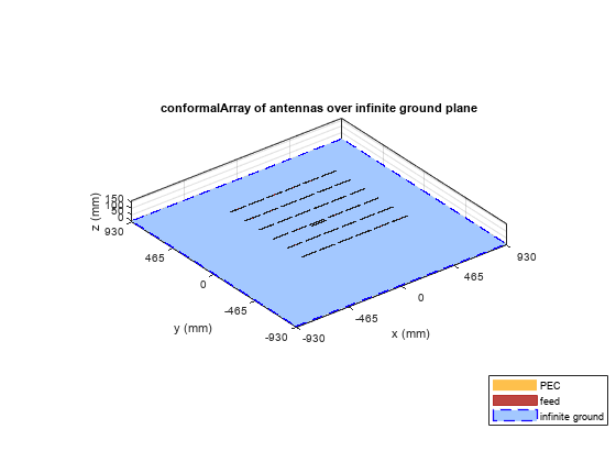
Create a conformal array using 36 dipole antennas and one infinite groundplane reflector antenna. View the array.

x = linspace(-0.4,0.4,6);
y = linspace(-0.4,0.4,6);
[X,Y] = meshgrid(x,y);
pos = [X(:) Y(:) 0.15*ones(numel(X),1)];
for i = 1:36
    element{i} = d;
end
element{37} = rf;
lwa = conformalArray(Element=element,ElementPosition=[pos; 0 0 0.15/2]);
show(lwa)

Figure contains an axes object. The axes object with title conformalArray of antennas over infinite ground plane, xlabel x (mm), ylabel y (mm) contains 112 objects of type patch, surface. These objects represent PEC, feed, infinite ground.

Drive only the reflector antenna with an amplitude of 1.

V = zeros(1,37);
V(end) = 1;
lwa.AmplitudeTaper = V;

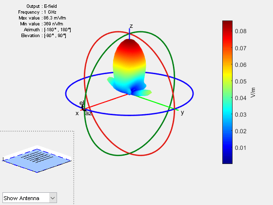
Compute the radiation pattern of the conformal array.

figure
pattern(lwa,1e9,Type='efield')

Figure contains an axes object and other objects of type uicontrol. The axes object contains 112 objects of type patch, surface. This object represents infinite ground.

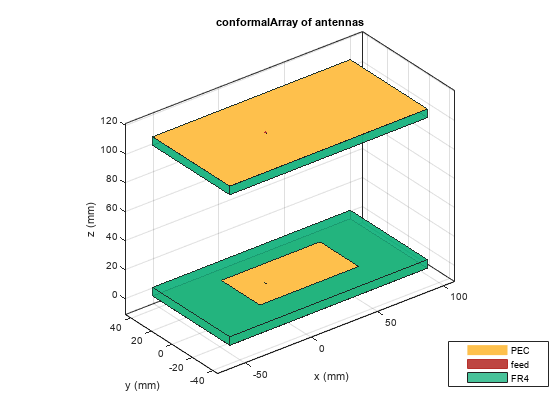
Create two patch microstrip antennas using dielectric substrate FR4. Tilt the second patch microstrip antenna by 180 degrees.

p1 = patchMicrostrip(Substrate=dielectric('FR4'));
p2 = patchMicrostrip(Substrate=dielectric('FR4'),Tilt=180);

Create and view a conformal array using the two patch microstrip antennas placed 11 cm apart.

c = conformalArray(ElementPosition=[0 0 0; 0 0 0.1100],Element={p1 p2});
show(c)

Figure contains an axes object. The axes object with title conformalArray of antennas, xlabel x (mm), ylabel y (mm) contains 12 objects of type patch, surface. These objects represent PEC, feed, FR4.

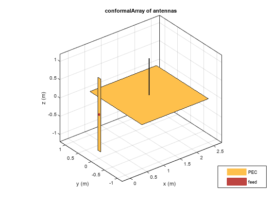
Create a conformal array using dipole and monopole antennas and display it.

c = conformalArray(Element={dipole monopole},...
    ElementPosition=[0 0 0; 1.5 0 0]);
show(c)

Figure contains an axes object. The axes object with title conformalArray of antennas, xlabel x (m), ylabel y (m) contains 7 objects of type patch, surface. These objects represent PEC, feed.

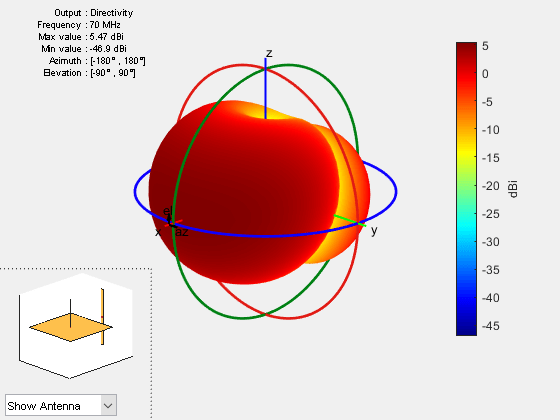
Plot the radiation pattern of the array at 70 MHz.

pattern(c,70e6)

Figure contains an axes object and other objects of type uicontrol. The axes object contains 7 objects of type patch, surface.

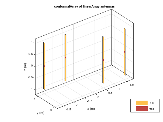
Create a subarray of linear arrays at different locations.

la = linearArray(ElementSpacing=1)
la = 
  linearArray with properties:

           Element: [1x1 dipole]
       NumElements: 2
    ElementSpacing: 1
    AmplitudeTaper: 1
        PhaseShift: 0
              Tilt: 0
          TiltAxis: [1 0 0]

subArr = conformalArray(Element=[la la],ElementPosition=[1 0 0; -1 1 0])
subArr = 
  conformalArray with properties:

            Element: [1x2 linearArray]
    ElementPosition: [2x3 double]
          Reference: 'feed'
     AmplitudeTaper: 1
         PhaseShift: 0
               Tilt: 0
           TiltAxis: [1 0 0]

show(subArr)

Figure contains an axes object. The axes object with title conformalArray of linearArray antennas, xlabel x (m), ylabel y (m) contains 12 objects of type patch, surface. These objects represent PEC, feed.

Create a linear array of dipoles with and element spacing of 1m.

la = linearArray(ElementSpacing=1);

Create a rectangular array of microstrip patch antennas.

ra = rectangularArray(Element=patchMicrostrip,RowSpacing=0.1,ColumnSpacing=0.1);

Create a subarray containing the above linear and rectangular arrays with changes in amplitude taper and phase shift values.

subArr = conformalArray(Element={la ra dipole},ElementPosition=[0 0 1.5; 0 0 0; 1 1 1],...
    AmplitudeTaper=[3 0.3 0.03],PhaseShift=[90 180 120]);
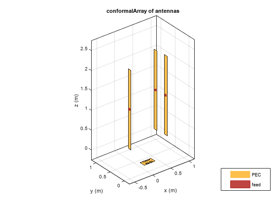
show(subArr)

Figure contains an axes object. The axes object with title conformalArray of antennas, xlabel x (m), ylabel y (m) contains 27 objects of type patch, surface. These objects represent PEC, feed.

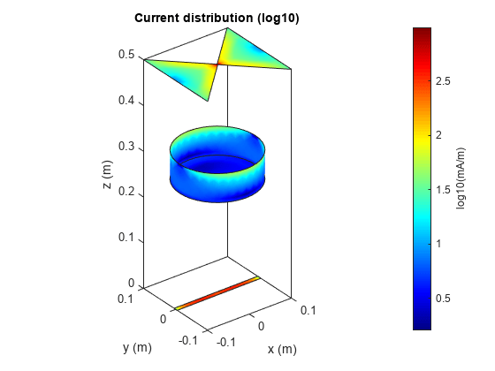
This example shows how to create a circular cavity structure as an element in a conformalArray and plot its surface current distribution.

Create Circular Cavity Antenna

Create a circular cavity antenna operating at 1 GHz using the design function and the cavityCircular element from the antenna catalog. Display the antenna.

f = 1e9;
lambda = 3e8/f;
ant = design(cavityCircular,f);
figure
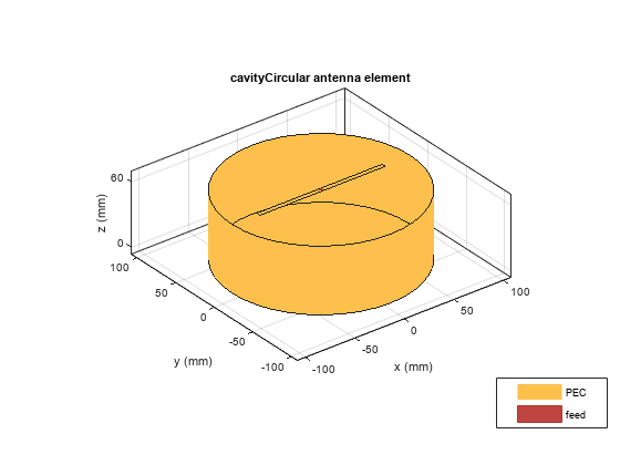
show(ant)

Figure contains an axes object. The axes object with title cavityCircular antenna element, xlabel x (mm), ylabel y (mm) contains 5 objects of type patch, surface. These objects represent PEC, feed.

Derive Backing Structure

Derive the circular cavity backing structure from the cavity antenna by specifying the 'Exciter' property as an empty array. Display the backing structure.

ant.Exciter = [];
figure
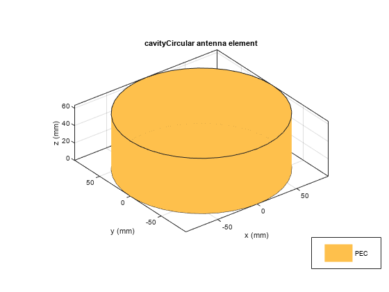
show(ant)

Figure contains an axes object. The axes object with title cavityCircular antenna element, xlabel x (mm), ylabel y (mm) contains 2 objects of type patch. This object represents PEC.

Create Conformal Array

Create and display a conformal array with circular cavity as one of its elements.

ca = conformalArray;
ca.Reference = "origin";
ca.ElementPosition = [0 0 0; 0 0 0.25; 0 0 0.5];
ca.Element = {ca.Element{1} ant ca.Element{2}};
figure
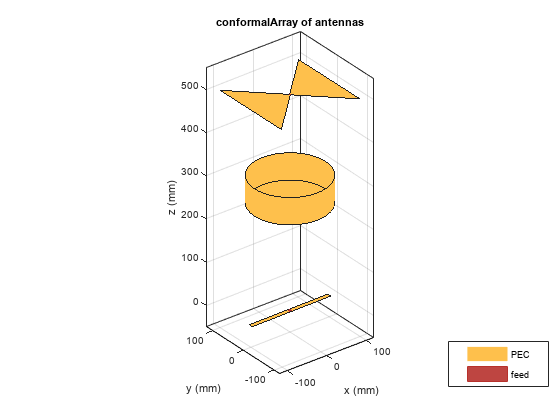
show(ca)

Figure contains an axes object. The axes object with title conformalArray of antennas, xlabel x (mm), ylabel y (mm) contains 8 objects of type patch, surface. These objects represent PEC, feed.

Plot Surface Current Distribution

Calculate the current at the feed location and plot the surface current distribution of the conformal array at 1 GHz.

If = feedCurrent(ca,f)
If = 1×2 complex

   0.0023 - 0.0005i   0.0029 + 0.0007i

figure
current(ca,f,Scale="log10")

Figure contains an axes object. The axes object with title Current distribution (log10), xlabel x (m), ylabel y (m) contains 7 objects of type patch.

More About

expand all

References

[1] Balanis, Constantine A. Antenna Theory: Analysis and Design. 3rd Ed. New York: John Wiley and Sons, 2005.
Version History

Introduced in R2016a