Sistemi elettrici
Scoprire gli esempi che illustrano la modellazione, il controllo e la simulazione di sistemi elettrici.
Categorie
- Circuiti elettrici in Simulink e Simscape
Esempi in evidenza di circuiti elettrici in Simulink® e Simscape™
- Batterie
Esempi di batterie
Esempi in primo piano
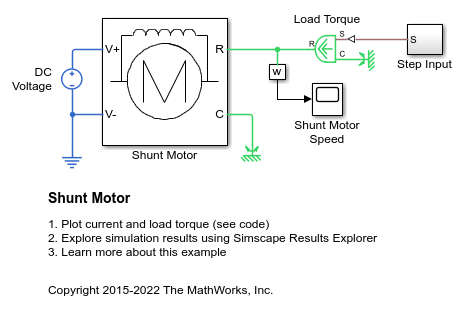
Shunt Motor
A model of a shunt motor. In a shunt motor, the field and armature windings are connected in parallel. Equivalent circuit parameters are armature resistance Ra = 110 Ohms, field resistance Rf = 2.46KOhms, and back emf coefficient Laf = 5.11. The back-emf is given by Laf*If*Ia*w, where If is the field current, Ia is the armature current, and w is the rotor speed in radians/s. The rotor inertia J is 2.2e-4kgm^2, and rotor damping B is 2.8e-6Nm/(radian/s).

Motore CC a magnete permanente
Questo esempio mostra come verificare le specifiche del produttore relative alla velocità a vuoto, alla corrente a vuoto e alla coppia di stallo di un motore CC utilizzando un test harness e i blocchi Simscape™.
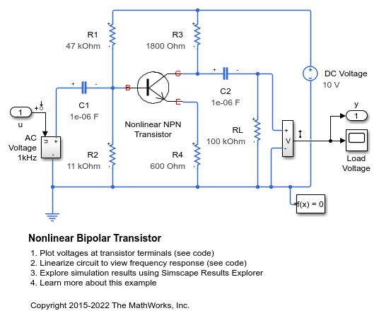
Transistor bipolare non lineare
Questo modello mostra l'implementazione di un transistor bipolare non lineare basato sul circuito equivalente di Ebers-Moll. R1 e R2 determinano il punto di funzionamento nominale, mentre il guadagno a piccolo segnale è determinato approssimativamente dal rapporto R3/R4. Sono stati scelti i condensatori di disaccoppiamento da 1 uF per presentare un'impedenza trascurabile a 1 kHz. Il modello è configurato per la linearizzazione in modo da poter generare una risposta in frequenza.
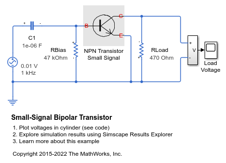
Small-Signal Bipolar Transistor
The use of a small-signal equivalent transistor model to assess performance of a common-emitter amplifier. The 47K resistor is the bias resistor required to set nominal operating point, and the 470 Ohm resistor is the load resistor. The transistor is represented by a hybrid-parameter equivalent circuit with circuit parameters h_ie (base circuit resistance), h_oe (output admittance), h_fe (forward current gain), and h_re (reverse voltage transfer ratio). Parameters set are typical for a BC107 Group B transistor. The gain is approximately given by -h_fe*470/h_ie =-47. The 1uF decoupling capacitor has been chosen to present negligible impedance at 1KHz compared to the input resistance h_ie, so the output voltage should be 47*10mV = 0.47V peak.
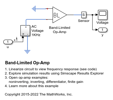
Band-Limited Op-Amp
How higher fidelity or more detailed component models can be built from the Foundation library blocks. The model implements a band-limited op-amp. It includes a first-order dynamic from inputs to outputs, and gives much faster simulation than if using a device-level equivalent circuit, which would normally include multiple transistors. This model also includes the effects of input and output impedance (Rin and Rout in the circuit), but does not include nonlinear effects such as slew-rate limiting.
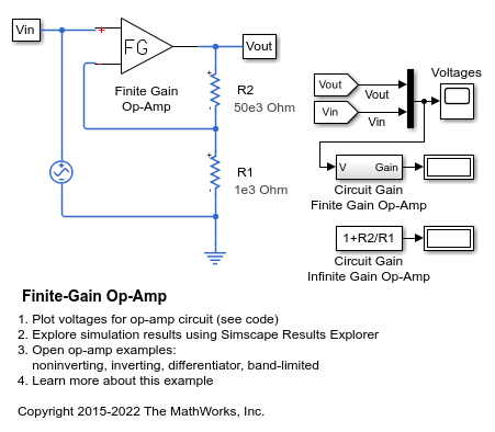
Finite-Gain Op-Amp
How higher fidelity or more detailed component models can be built from the Foundation library blocks. The Op-Amp block in the Foundation library models the ideal case whereby the gain is infinite, input impedance infinite, and output impedance zero. The Finite Gain Op-Amp block in this example has an open-loop gain of 1e5, input resistance of 100K ohms and output resistance of 10 ohms. As a result, the gain for this amplifier circuit is slightly lower than the gain that can be analytically calculated if the op-amp gain is assumed to be infinite.
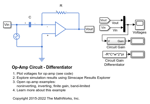
Op-Amp Circuit - Differentiator
A differentiator, such as might be used as part of a PID controller. It also illustrates how numerical simulation issues can arise in some idealized circuits. The model runs with the capacitor series parasitic resistance set to its default value of 1e-6 Ohms. Setting it to zero results in a warning and a very slow simulation. See the User's Guide for further information.

Circuito op-amp - Amplificatore invertente
Questo esempio mostra un modello di un circuito op-amp invertente standard. Il guadagno è dato da -R2/R1. Con R1 = 1K Ohm e R2 = 10K Ohm, la tensione di input di 0,1 V picco-picco viene amplificata a 1 V picco-picco. Il blocco Op-Amp implementa un dispositivo ideale (a guadagno infinito), ottenendo quindi tale guadagno indipendentemente di output.
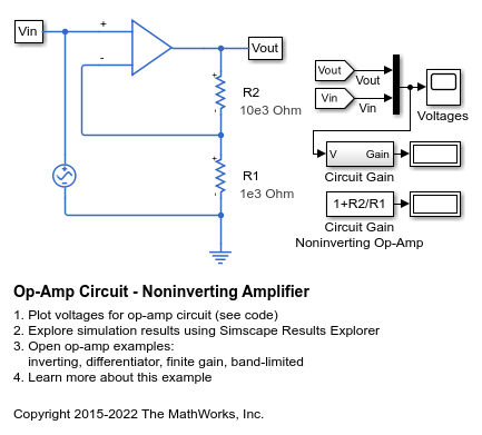
Circuito op-amp - Amplificatore non invertente
Questo modello mostra un circuito op-amp non invertente. Il guadagno è dato da 1+R2/R1 e, con i valori impostati a R1=1K Ohm e R2=10K Ohm, la tensione di ingresso da 0,1V picco-picco viene amplificata a 1,1V picco-picco. Poiché il blocco Op-Amp implementa un dispositivo ideale (ossia a guadagno infinito), questo guadagno si ottiene indipendentemente dal carico di output.
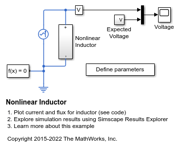
Nonlinear Inductor
An implementation of a nonlinear inductor where inductance depends on current. A tanh function defines the nonlinear flux-current relationship. The flux saturates for large currents, which can occur, for example, in iron core inductors.

Rettificatore a ponte full-wave
Questo esempio mostra come dimensionare un condensatore per un carico specifico in un trasformatore che converte 120 V in CA in 12 V in CC. Il sistema è modellato come un trasformatore CA ideale abbinato a un rettificatore a ponte full-wave.
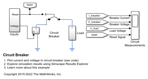
Circuit Breaker
Model a circuit breaker. The electromechanical breaker mechanism is approximated with a first-order time constant, and it is assumed that the mechanical force is proportional to load current. This simple representation is suitable for use in a larger model of a complete system. When the 20V supply is applied at one second, it results in a current that exceeds the circuit breaker current rating, and hence the breaker trips. The reset is then pressed at three seconds, and the voltage is ramped up. The breaker then trips just beyond the circuit breaker current rating.

Solenoide
Questo esempio mostra un solenoide con ritorno a molla. Il solenoide è modellato come un'induttanza il cui valore L dipende dalla posizione x dello stantuffo. La forza elettromotrice inversa (EMF) per un'induttanza variabile nel tempo è data da:
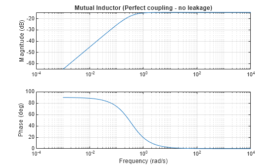
A Comparison of the Mutual Inductor and Ideal Transformer Library Blocks
The differences in behavior between the Mutual Inductor and Ideal Transformer blocks in the Simscape™ Foundation Library. These two blocks both represent the same system of electromagnetically-coupled windings but make different simplifying assumptions. It is important to understand the assumptions and how they impact model fidelity as a function of frequency. With this, you can make an informed decision about which block to use in a model of your circuit.

Operating Point RLC Transient Response
The response of a DC power supply connected to a series RLC load. The goal is to plot the output voltage response when a load is suddenly attached to the fully powered-up supply. This is done using a Simscape operating point.