Design Rigid Interface Specifications for Conserving Connections
You can design rigid interface specifications for conserving connections and lock down
connection names and types by using Simulink.ConnectionBus and Simulink.ConnectionElement objects. Then, when you apply a rigid specification to
a Simscape Bus or Connection Port block, the block ports become
typed by the interface and do not accept connections to a different domain type. This
functionality helps you ensure the correct connection types within your model architecture.
For example, if you design a 6-pin rigid interface and apply it to two Simscape
Bus blocks in your model, these blocks can be connected to each other, but not to a
block with a 9-pin interface.
Before you can apply a rigid interface specification to a Simscape Bus or
Connection Port block, you need to have a
Simulink.ConnectionBus object in your base workspace or a data dictionary.
You can construct or modify these objects:
Using MATLAB® commands. For more information, see Create Connection Bus and Connection Element Objects Using MATLAB Commands.
Using the Simulink® Type Editor.
Using the Model Explorer.
Create Connection Bus Objects Using the Type Editor
Before you can apply a rigid interface specification to a Simscape Bus or
Connection Port block, you need to have a
Simulink.ConnectionBus object in your base workspace or a data
dictionary.
In this example, define a rigid interface with one mechanical
translational and one electrical port by creating a ConnectionBus object
named MechElec.
Open the Type Editor, which is a tool that lets you create, modify, and manage types, such as bus objects. At the MATLAB command prompt, enter
typeeditor.Tip
You can also open the Type Editor directly from a Simscape Bus or Connection Port block dialog box. Under Type Assistant, set Mode to
Connection Bus
								object
and click the Edit button. The Type Editor opens in the model window.How you create types in the Type Editor depends on whether you open the Type Editor in the context of a model window or as a standalone window. For more information, see Create Types Using Type Editor.
In the Type Editor, in the Add gallery, click the Connection Bus button.
A
ConnectionBusobject with a default name appears in the middle pane and its default properties appear in the Simulink.ConnectionBus dialog pane.Specify the name for the
ConnectionBusobject using the Name property. In this example, name theConnectionBusobjectMechElec.Optionally, add a description for the
ConnectionBusobject using the Description property.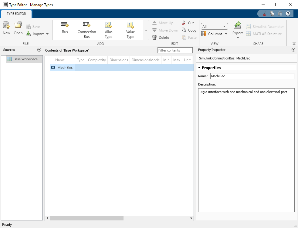
Tip
By default, when you create objects or edit properties, all changes are applied automatically.
Expand the Add gallery and click the Connection Element button.
A connection element with a default name and default properties is created in the
MechElecConnectionBusobject. The connection element appears in the middle pane nested under theMechElecConnectionBusobject.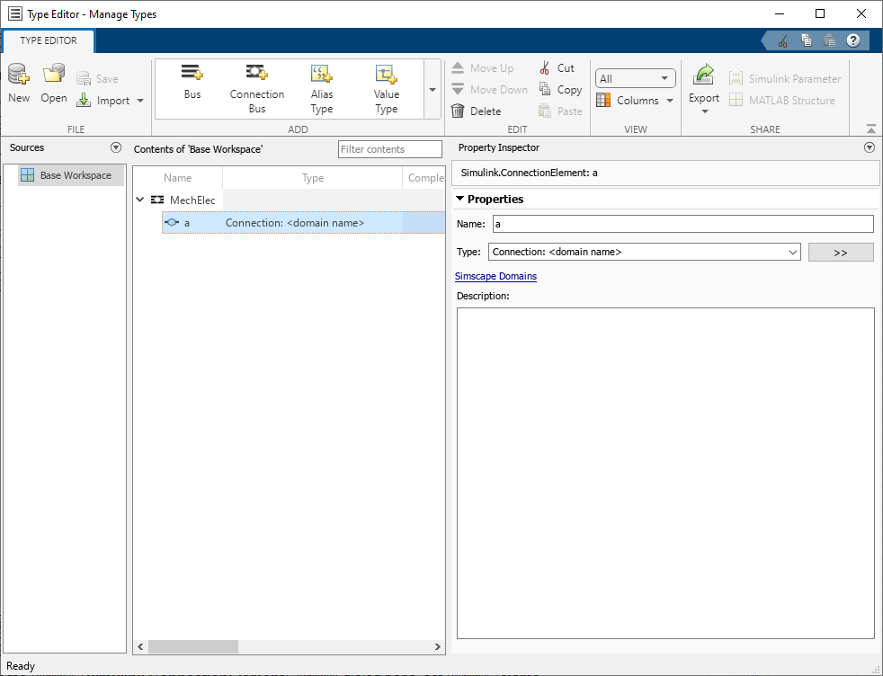
In the Simulink.ConnectionElement dialog pane, set Name to
mech.From the Type drop-down list, select
Connection:
              foundation.mechanical.translational.translational
, which corresponds to the Foundation mechanical translational domain.Tip
For a list of Foundation domain types, see Domain-Specific Line Styles.
Optionally, add a description for the
ConnectionElementobject using the Description property.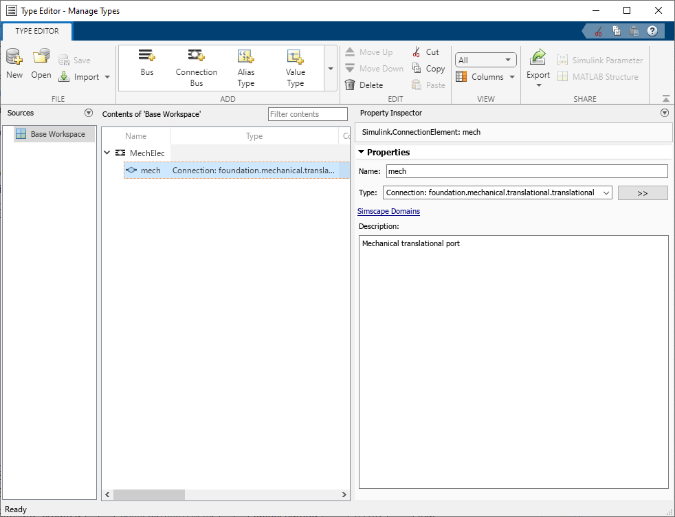
Similarly, create a
ConnectionElementobject namedelecthat corresponds to the electrical port.You now have a
ConnectionBusobject with one translational mechanical and one electrical connection port.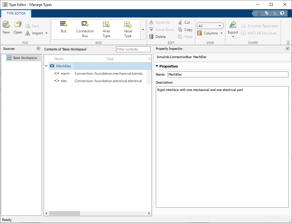
Save the
ConnectionBusobject to a MAT-file calledMechElec.If you do not save a
ConnectionBusobject, then when you reopen a model that uses thatConnectionBusobject, you need to recreate the object. You save and loadConnectionBusobjects similar toSimulink.Busobjects. For more information, see Save Simulink Bus Objects.
Apply a Rigid Interface Specification to a Simscape Bus Block
In this example, you apply the rigid interface specification, which you created in Create Connection Bus Objects Using the Type Editor, to a Simscape
Bus block. Before starting the exercise, make sure that you have the
MechElec object in your base workspace or a data dictionary.
Create a new model or open an existing model containing blocks with both electrical and mechanical translational ports.
Open the Simscape > Utilities block library and add a Simscape Bus block to the model diagram.
Double-click the Simscape Bus block.
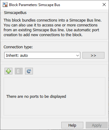
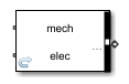
From the drop-down list under Connection type, select
Bus: MechElecand click Apply. Note that the block now has two children ports,mechandelec, according to the interface definition.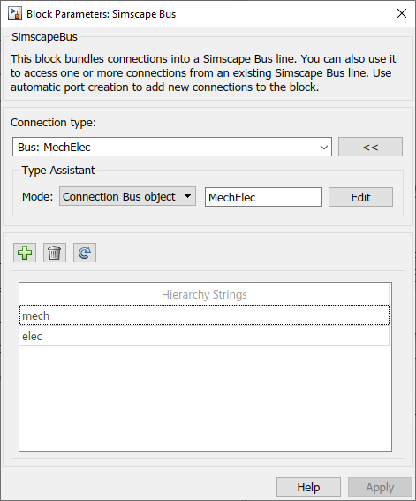
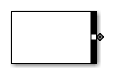
These ports appear under Hierarchy Strings in the block dialog, and the block icon changes as well to indicate that the block is a rigid bus.
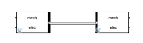
Add a second Simscape Bus block and apply the same interface definition to it. You can do this either by repeating the previous steps or by copying the first block.
Flip the second block to face the first one and connect the bus ports of the two blocks. You can connect these bus ports because the Simscape Bus blocks use the same interface definition, and therefore have identical children ports. The connection line style (double line) indicates a rigid bus connection.
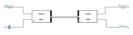
You can now connect electrical and mechanical translational ports on other blocks in the model to the children ports of the Simscape Bus blocks, for example: