Main Content

customAntennaStl

Create custom antenna 3-D geometry using STL files

Since R2020a

Description

The customAntennaStl object creates a 3-D antenna geometry and mesh using Stereolithography (STL) files. The STL files are used to define any 3-D surface in the form of points and triangles.

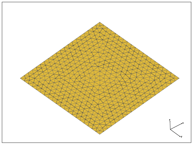
Top view of plateMesh.stl, a default custom antenna 3-D geometry file used in customAntennaStl object.

Creation

Description

example

ca = customAntennaStl returns a 3D antenna represented by a custom geometry, based on the STL file specified.

Properties

expand all

Name of the STL file where the structure resides, specified as character vector.

Example: antenna = customAntennaStl('FileName','plate.stl')

Example: antenna = customAntennaStl; antenna.FileName = 'plate.stl'

Data Types: char

Units used in STL file, specified as a character vector.

Example: 'Units','mm'

Data Types: char

This property is read-only.

Antenna feed location in Cartesian coordinates, specified as a three-element real vector. The three-element vector are the X-, Y-, and Z-coordinates, respectively.

Note

FeedLocation property displays the antenna feed location you set using the createFeed function.

Data Types: double

Excitation amplitude of antenna elements, specified as scalar double.

Example: 'AmplitudeTaper','1.8'

Data Types: double

Phase shift for the antenna elements, specified as a scalar in degrees.

Example: 'PhaseShift',10

Data Types: double

Use the STL file directly as a mesh for analysis. The value can be either 0 or 1.

Example: 'UseFileAsMesh',1

Data Types: logical

Tilt angle of the antenna, specified as a scalar or vector with each element unit in degrees. For more information, see Rotate Antennas and Arrays.

Example: Tilt=90

Example: Tilt=[90 90],TiltAxis=[0 1 0;0 1 1] tilts the antenna at 90 degrees about the two axes defined by the vectors.

Note

The wireStack antenna object only accepts the dot method to change its properties.

Data Types: double

Tilt axis of the antenna, specified as:

  • Three-element vector of Cartesian coordinates in meters. In this case, each coordinate in the vector starts at the origin and lies along the specified points on the X-, Y-, and Z-axes.

  • Two points in space, each specified as three-element vectors of Cartesian coordinates. In this case, the antenna rotates around the line joining the two points in space.

  • A string input describing simple rotations around one of the principal axes, 'X', 'Y', or 'Z'.

For more information, see Rotate Antennas and Arrays.

Example: TiltAxis=[0 1 0]

Example: TiltAxis=[0 0 0;0 1 0]

Example: TiltAxis = 'Z'

Data Types: double

Object Functions

showDisplay antenna, array structures or shapes
infoDisplay information about antenna or array
createFeedCreate feed location for customAntennaStl object
axialRatioAxial ratio of antenna
beamwidthBeamwidth of antenna
chargeCharge distribution on antenna or array surface
currentCurrent distribution on antenna or array surface
impedanceInput impedance of antenna; scan impedance of array
meshMesh properties of metal, dielectric antenna, or array structure
meshconfigChange mesh mode of antenna structure
patternRadiation pattern and phase of antenna or array; Embedded pattern of antenna element in array
patternAzimuthAzimuth pattern of antenna or array
patternElevationElevation pattern of antenna or array
returnLossReturn loss of antenna; scan return loss of array
sparametersCalculate S-parameter for antenna and antenna array objects
vswrVoltage standing wave ratio of antenna
rcsCalculate and plot radar cross section (RCS) of platform, antenna, or array
EHfieldsElectric and magnetic fields of antennas; Embedded electric and magnetic fields of antenna element in arrays

Examples

collapse all

Create a custom 3-D antenna using customAntennaStl object.

c = customAntennaStl('Filename','plateMesh.stl','Units','m');

Create antenna feed and calculate the antenna impedance at 110 GHz.

c.createFeed([0,0,0],1);
Z = impedance(c,110e6)
Z = 0.0287 +34.3704i
disp(c)
  customAntennaStl with properties:

          FileName: 'plateMesh.stl'
             Units: 'm'
      FeedLocation: [0 0 0]
    AmplitudeTaper: 1
        PhaseShift: 0
     UseFileAsMesh: 0
              Tilt: 0
          TiltAxis: [1 0 0]

Display the structure of custom 3-D antenna.

show(c)

Figure contains an axes object. The axes object with xlabel x (m), ylabel y (m) contains 3 objects of type patch, surface. These objects represent PEC, feed.

Create a customAntennaStl object using the specified STL file.

ant = customAntennaStl
ant = 
  customAntennaStl with properties:

          FileName: []
             Units: 'm'
      FeedLocation: []
    AmplitudeTaper: 1
        PhaseShift: 0
     UseFileAsMesh: 0
              Tilt: 0
          TiltAxis: [1 0 0]

ant.FileName ='patchMicrostrip_ColumnFeed.stl'
ant = 
  customAntennaStl with properties:

          FileName: 'patchMicrostrip_ColumnFeed.stl'
             Units: 'm'
      FeedLocation: []
    AmplitudeTaper: 1
        PhaseShift: 0
     UseFileAsMesh: 0
              Tilt: 0
          TiltAxis: [1 0 0]

Specify FeedLocation and NumEdges in the createFeed function. The edges are selected based on distance between feed location and midpoints of the edges. Edges can be single feed or a closed polygon.

ant.createFeed([-0.018750000000000 0 0],8)
show (ant)

Figure contains an axes object. The axes object with xlabel x (mm), ylabel y (mm) contains 3 objects of type patch, surface. These objects represent PEC, feed.

Plot the current distribution at 1.75 GHz.

figure
current(ant,1.75e9,'Scale','log')

Figure contains an axes object. The axes object with title Current distribution (log), xlabel x (m), ylabel y (m) contains 3 objects of type patch.

Calculate the impedance at 1.75 GHz.

z = impedance(ant,1.75e9)
z = 85.7298 -52.7332i

Create a customAntennaStl object.

ant = customAntennaStl;

Import the STL files.

ant.FileName = 'patchMicrostrip_ColumnFeed.stl';

Create the antenna feed using UI figure window.

createFeed(ant);

Figure Create Feed contains an axes object and other objects of type uipanel. The axes object with title Select a Feeding Edge or Polygon., xlabel x (mm), ylabel y (mm) is empty.

The UI figure window consists of two panes, the Slice Antenna panel and the Add Feed pane.

Click the Slicer Mode, then click YZ to select that as the plane along which to slice your antenna.

Select the region you want to hide and then click Hide to hide the selected region.

Repeat the process until you reach the region of interest.

Select Select a Feeding Edge or Polygon under the Add Feed pane to select the desired feeding edge or feeding polygon.

Select the edges of the column that forms a closed polygon. The selected edges must be connected to other edges, else the UI figure window will display an error.

Click OK to define the selected edges as feeding edges and the structure with the feed is displayed.

The FeedLocation is displayed.

Verify the location of the antenna feed in the commandline.

ant
ant = 
  customAntennaStl with properties:

          FileName: 'patchMicrostrip_ColumnFeed.stl'
             Units: 'm'
      FeedLocation: []
    AmplitudeTaper: 1
        PhaseShift: 0
     UseFileAsMesh: 0
              Tilt: 0
          TiltAxis: [1 0 0]

References

[1] Balanis, C. A. Antenna Theory. Analysis and Design. 3rd Ed. Hoboken, NJ: John Wiley & Sons, 2005.

Version History

Introduced in R2020a