customAntenna
Description
The customAntenna object lets you create an antenna from a custom
shape. You can use the basic 2-D and 3-D shapes from the catalog and perform geometric
operations on them to create a custom shape. You can also use the triangulation or shape
vertices to create custom shapes. You assign a feed to a location on the shape to convert it
into an antenna. Perform port, surface, and field analysis on this antenna. You can use this
antenna as an exciter for the cavity and reflector type backing structures, element in the
arrays, element for the installed antenna analysis, or element in the plane wave excitation
environment.
Creation
Description
c = customAntenna
c = customAntenna(PropertyName=Value)PropertyName is the property
name and Value is the corresponding value. You can specify several
name-value arguments in any order as PropertyName1=Value1,
..., PropertyNameN=ValueN. Properties that you
do not specify retain their default values.
For example, c =
customAntenna(Shape=shape.Rectangle(Metal="Copper")) creates a rectangular
copper shape and default values for other properties.
Properties
Object Functions
axialRatio | Calculate and plot axial ratio of antenna or array |
bandwidth | Calculate and plot absolute bandwidth of antenna or array |
beamwidth | Beamwidth of antenna |
charge | Charge distribution on antenna or array surface |
createFeed | Create feed location for custom antenna |
current | Current distribution on antenna or array surface |
efficiency | Calculate and plot radiation efficiency of antenna or array |
EHfields | Electric and magnetic fields of antennas or embedded electric and magnetic fields of antenna element in arrays |
feedCurrent | Calculate current at feed for antenna or array |
impedance | Calculate and plot input impedance of antenna or scan impedance of array |
info | Display information about antenna, array, or platform |
memoryEstimate | Estimate memory required to solve antenna or array mesh |
mesh | Generate and view mesh for antennas, arrays, and custom shapes |
meshconfig | Change meshing mode of antenna, array, custom antenna, custom array, or custom geometry |
msiwrite | Write antenna or array analysis data to MSI planet file |
optimize | Optimize antenna and array catalog elements using SADEA or TR-SADEA algorithm |
pattern | Plot radiation pattern of antenna, array, or embedded element of array |
patternAzimuth | Azimuth plane radiation pattern of antenna or array |
patternElevation | Elevation plane radiation pattern of antenna or array |
peakRadiation | Calculate and mark maximum radiation points of antenna or array on radiation pattern |
rcs | Calculate and plot monostatic and bistatic radar cross section (RCS) of platform, antenna, or array |
resonantFrequency | Calculate and plot resonant frequency of antenna |
returnLoss | Calculate and plot return loss of antenna or scan return loss of array |
show | Display antenna, array, AI-based antenna, platform, or shape |
sparameters | Calculate S-parameters for antenna or array |
stlwrite | Write mesh information to STL file |
vswr | Calculate and plot voltage standing wave ratio (VSWR) of antenna or array element |
Examples
This example shows how to build a horn antenna using 2D and 3D shapes from the shapes catalog and customAntenna object. Follow a two step approach to create a horn antenna. Divide a horn antenna into two parts - a waveguide and a horn taper. Join them to create the horn shape. Then use this shape to create the horn antenna. Add feed to this antenna and plot its directivity pattern.
Define the dimensions of the horn and feed region in meters.
length = 0.0095;
width = 0.019;
height = 0.05;
feedHeight = 0.0048;
feedWidth = 1e-4;
feedOffset = [-0.0155 0];
flarelength = 0.102;
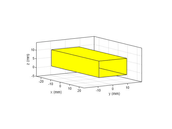
Use shape.Box object to create a box.
wShape = shape.Box(Length=length, Width=width,...
    Height=height);
Remove one face of the box to create a hollow box. Orient the shape appropriately.
removeFaces(wShape,2);

rotate(wShape,90,[0 0 0],[0 1 0]);

translate(wShape,[0 0 length/2]);
Create a horn taper by linearly extruding and orienting a rectangular shape.
rect = shape.Rectangle(Length=length, Width=width);
show(rect)

hornTaper = extrudeLinear(rect,flarelength, Scale=...
[3.5579 3], NumSegments=1);
show(hornTaper)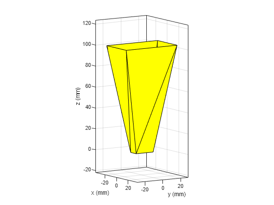
rotate(hornTaper,90,[0 0 0],[0 1 0]);
translate(hornTaper,[height/2 0 length/2]);
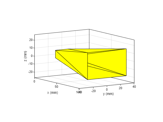
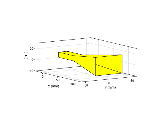
Join the waveguide and horn taper shapes to form the horn shape.
hornShape = add(wShape,hornTaper, RetainShape=1);
show(hornShape)
Create a rectangular feed probe and orient it.
feedProbe = shape.Rectangle(Length=feedHeight, Width=feedWidth);
rotate(feedProbe,90,[0 0 0],[0 1 0]);
translate(feedProbe,[feedOffset(1) feedOffset(2) feedHeight/2]);

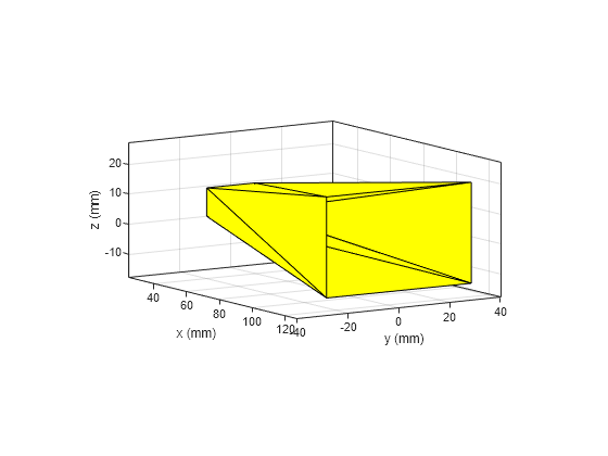
Use the customAntenna object to create the horn antenna from the horn shape and add feed to it.
ant = customAntenna(Shape=hornShape);
ant = createFeed(ant,[feedOffset 0],1, FeedShape=feedProbe);
show(ant)

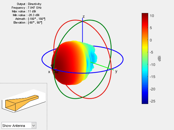
Plot the directivity pattern of the horn antenna at 7.847 GHz.
pattern(ant,7.847e9)
This example shows how to create a custom antenna from an element in the antenna catalog.
Create a default horn antenna and manually mesh it with a maximum edge length of 0.01 m.
ant = horn;
feedLoc = ant.FeedLocation;
m = mesh(ant,MaxEdgeLength=0.01);
Use triangulation to store the mesh data of this horn antenna.
p = m.Points';
t = m.Triangles';
tr = triangulation(t(:,1:4),p)
tr =
  triangulation with properties:

              Points: [327×3 double]
    ConnectivityList: [602×4 double]
Use shape.Custom3D to generate a horn shape from triangulation data. Visualize the shape.
hornShape = shape.Custom3D(tr);
show(hornShape)

Create a box.
hole = shape.Box(Length=0.012, Width=0.004, Height=0.005);
translate(hole,[-hole.Length 0 (hole.Length/2)+hole.Height/2]);

Cut a hole in the horn geometry by subtracting the box from it. Visualize the custom shape.
hornShape = subtract(hornShape,hole);
show(hornShape)

Use customAntenna to create a custom antenna from the custom horn shape. Add feed to it and visualize the antenna.
ant = customAntenna(Shape=hornShape);
[~] = createFeed(ant,feedLoc,1);
figure
show(ant)
title("Custom Horn Antenna")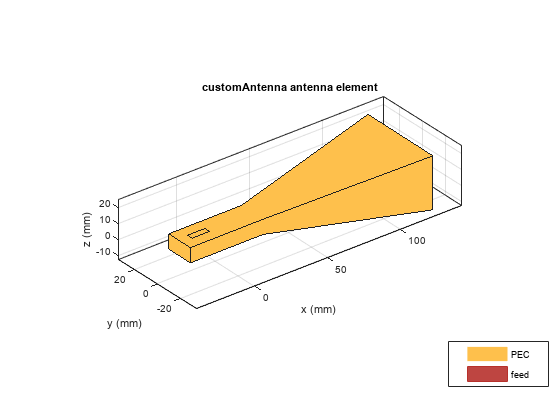
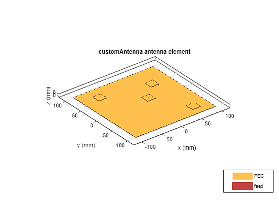
This example shows how to create a conformal array of 4 custom microstrip patch antennas on a common ground plane.
Create ground plane, patch, and feed shape. Add the patch and feed shapes to generate the patch antenna shape.
gnd = shape.Rectangle(Length=0.2, Width=0.2);
patch1 = shape.Rectangle(Length=0.02, Width=0.02);
feed1 = shape.Rectangle(Length=0.006, Width=0.001);
[~] = rotateY(feed1,90);
[~] = translate(feed1,[0 0 feed1.Length/2]);
[~] = translate(patch1,[0 0 feed1.Length]);
ant1 = patch1 + feed1;
Create 3 identical patch antenna shapes from the initial design.
ant2 = copy(ant1);
ant3 = copy(ant1);
ant4 = copy(ant1);
[~]= translate(ant1,[0.01 0 0]);
[~]= translate(ant2,[0.06 -0.08 0]);
[~]= translate(ant3,[0.05 0.04 0]);
[~]= translate(ant4,[-0.065 0.06 0]);
Add all the antenna shapes and the ground plane shape to generate a conformal array configuration.
antShape = ant1 + ant2 + ant3 + ant4;
arrayShape = antShape + gnd;
Use this conformal array shape in a customAntenna and add feed points to the array elements. Visualize the conformal array.
conformalArrayAntenna= customAntenna(Shape=arrayShape);
[~] = createFeed(conformalArrayAntenna,[0.01 0 0; 0.06 -0.08 0; 0.05 0.04 0; -0.065 0.06 0],[1 1 1 1]);
show(conformalArrayAntenna)
This example shows how to create a custom antenna with multiple dielectric substrates using 2-D and 3-D shapes. To simplify the design process, divide the antenna into metal and dielectric layers. Define the dimensions in meters of elements in each layer.
% Ground plane
gndLength = 0.014;
gndWidth = 0.016;

% Substrates
lengthFR4 = 0.024;
widthFR4 = 0.016;
lengthTeflon = 0.01;
widthTeflon = 0.006;
substrateHeight = 0.004;

% Middle layer patches and strips
midPatchLength = 0.012;
midPatchWidth = 0.006;
horzStripLength = 0.014;
vertStripLength = 0.004;
stripWidth = 0.002;

% Top layer patch
topPatchLength = 0.006;
topPatchWidth = 0.005;
Create substrate shapes using the shape.Box object. Orient the shapes using the translate function.
sub1 = shape.Box(Name="FR4 Substrate", Length=lengthFR4, Width=widthFR4,...
    Height=substrateHeight, Dielectric="FR4");
[~] = translate(sub1,[0 0 substrateHeight/2]);

sub2 = shape.Box(Name="Teflon Substrate", Length=lengthTeflon, Width=widthTeflon,...
    Height=substrateHeight, Dielectric="Teflon");
[~] = translate(sub2,[lengthTeflon/2-lengthFR4/2+gndLength 0 1.5*substrateHeight]);
Create middle layer metal patch and strip shapes using the shape.Rectangle object. Orient the shapes using the translate function.
midPatch1 = shape.Rectangle(Name="Middle Layer Patch - 1", Length=0.012, Width=0.006,...
    Metal="PEC");
[~] = translate(midPatch1,[midPatchLength/2-lengthFR4/2 -midPatchWidth/2+widthFR4/2 0]);

midPatch2 = shape.Rectangle(Name="Middle Layer Patch - 2", Length=0.012, Width=0.006,...
    Metal="Copper");
[~] = translate(midPatch2,[midPatch2.Length/2-lengthFR4/2 midPatchWidth/2-widthFR4/2 0]);

horzStrip = shape.Rectangle(Name="Horizontal Strip", Length=horzStripLength, Width=stripWidth,...
    Metal="Copper");
[~] = translate(horzStrip,[horzStripLength/2-lengthFR4/2 0 0]);

vertStrip = shape.Rectangle(Name="Vertical Strip", Length=vertStripLength, Width=stripWidth,...
    Metal="Copper");
[~] = rotateY(vertStrip,90);
[~] = translate(vertStrip,[-lengthFR4/2+horzStripLength 0 vertStripLength/2]);
Create the top layer metal patch shape using the shape.Rectangle object. Orient the shape using the translate function.
topPatch = shape.Rectangle(Name="Top Layer Patch", Length=topPatchLength, Width=topPatchWidth,...
    Metal="Copper");
[~] = translate(topPatch,[topPatchLength/2-lengthFR4/2+gndLength 0 2*substrateHeight]);
Create the ground plane shape using the shape.Rectangle object. Orient the shape using the translate function.
gndLayer = shape.Rectangle(Name="Ground Plane", Length=gndLength, Width=gndWidth,...
    Metal="Copper");
[~] = translate(gndLayer,[gndLength/2-lengthFR4/2 0 0]);
Add the patches, strips, and ground plane to create the overall metal layer of the antenna. View the overall metal structure.
midLayer = midPatch1 + horzStrip + midPatch2 + vertStrip;
[~] = translate(midLayer,[0 0 substrateHeight]);
metalShape = topPatch + midLayer + gndLayer;
figure
show(metalShape)
title("Antenna Metal Layer with Ground")
view([-35 18])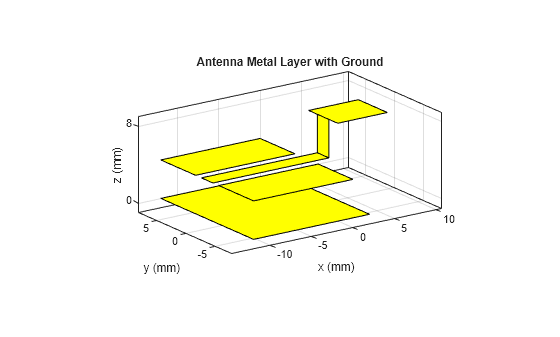
Add the substrate shapes to form the substrate layer.
substrate = sub1 + sub2;
Add substrate layer to the metal structure to create the antenna shape.
antShape = addSubstrate(metalShape,substrate);
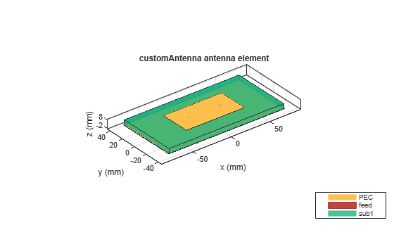
Use this shape to set the Shape property of the customAntenna object. Use the createFeed function to add a feed point to the antenna. View the antenna.
ant = customAntenna(Shape=antShape);
[~] = createFeed(ant,[-0.012 0 0.004],1);
figure
show(ant)
title("Antenna with Multiple Dielectric Substrates")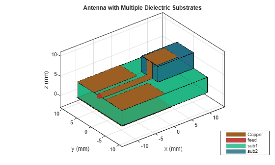
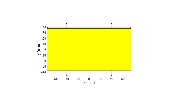
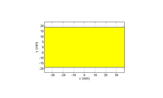
Create ground, substrate, patch, and feed shapes.
gnd = shape.Rectangle(Length=0.15,Width=0.075);
show(gnd)
sub = shape.Box(Length=0.15,Width=0.075,Height=0.006,Dielectric="FR4");
translate(sub,[0 0 sub.Height/2]);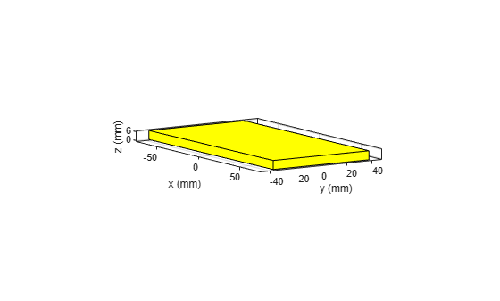
patch = shape.Rectangle(Length=0.075,Width=0.0375);
feed = shape.Rectangle(Length=0.006,Width=0.002);
translate(patch,[0 0 0.006]);
[~] = rotateY(feed,90);
feed2 = copy(feed);
Create a patch antenna using the shapes and specify the voltage and phase for each feed point.
[~] = translate(feed,[-0.02 0 feed.Length/2]);
[~] = translate(feed2,[0.02 0 feed.Length/2]);
ant_patch = add(gnd,patch);
ant_patch = add(ant_patch,feed);
ant_patch = add(ant_patch,feed2);
ant_sub = addSubstrate(ant_patch,sub);
ant = customAntenna(Shape=ant_sub);
[~] = createFeed(ant,[-0.02 0 0; 0.02 0 0],[1 1]);
ant.FeedVoltage = [1 1];
ant.FeedPhase = [90 180];
figure
show(ant)
Version History
Introduced in R2023bSee Also
Objects
Functions
Topics
- Design And Analyze Spherically Capped Biconical Antenna
- Analysis of Ultrawideband Trident Inset-Fed Monopole Antenna with Conical Ground
- Analyze Edge-Wall Slotted Waveguide Array Antenna for High-Frequency Applications
- Analysis of Basic Delta Loop Antenna over Ground
- Rotate Antennas and Arrays
- Feed Model
- Port Analysis
- Surface Analysis
- Field Analysis
- Far-field Terminologies
- Meshing
- Electrical Length of Antenna